
3D Ultrasonic Imaging of Concrete: FMC Technology Explained
Concrete remains the most widely used building material on the planet, and a large share of the infrastructure erected with it is now getting old. Bridges, dams, tunnels and nuclear facilities all require condition assessment that does not involve drilling cores out of them. Imaging ultrasonic testing gives inspectors a way to peer into a concrete structure and view reinforcement, voids, delaminations and cracks as two- and three-dimensional images.
This article explains how today’s ultrasonic tomography instruments for concrete are built. It describes the low-frequency dry-point-contact (DPC) transducers behind them, the 3D Full Matrix Capture (3D-FMC) data acquisition principle, reconstruction with the Total Focusing Method (TFM), pulse compression for very thick structures, 3D visualization modes and the measurement of crack depth.
Basis of this article
This article is adapted from two conference papers by the development team behind the ultrasonic tomography instruments described here (ACS-Solutions GmbH, Saarbrücken, Germany): “New trends in the ultrasonic imaging of concrete structures by means of 3D-FMC technology”, presented at NDT-CE 2022, the International Symposium on Non-Destructive Testing in Civil Engineering, Zurich, Switzerland, in August 2022, and “Advanced tomographic imaging techniques for quality assessment of concrete structures by means of ultrasound”, presented at NDE NucCon 2023, the International Conference on Non-destructive Evaluation of Concrete in Nuclear Applications, Espoo, Finland, in January 2023. The test results shown were recorded on real reference objects, including the reference blocks of the Federal Institute for Materials Research and Testing (BAM, Germany) at the Horstwalde test site. The article text and the instrument specifications were reviewed and updated in 2026 to reflect the current generation of ultrasonic tomographs.
What this article covers
- How modern ultrasonic tomographs for concrete are built and why they rely on dry-point-contact (DPC) transducers rather than gel-coupled probes
- How 3D-FMC data acquisition and TFM reconstruction build a three-dimensional image at every measuring position
- Why the measurement electronics and the processing unit are kept separate, and what that means for automated and robotic inspection
- How pulse compression stretches the inspection range on thick structures — demonstrated on a concrete block with a wall thickness of 4 m
- Which 3D visualization and rendering modes are available (Compound B- and D-scans, area scans, ISO surface, MIP, texture mapping)
- How the matrix aperture measures the depth of open surface cracks using diffraction signals
Contents
- 1. Ultrasonic imaging of concrete: an introduction
- 2. Design and operating principle of modern ultrasonic instruments for concrete
- 3. Advanced signal processing methods that extend the testing range
- 4. Types of 3D visualization and result presentation
- 5. Evaluating crack depth
- 6. Summary and outlook
- 7. Delta Test Technologies and 3D-FMC instruments
- 8. FAQ
- 9. References
1. Ultrasonic imaging of concrete: an introduction
Imaging ultrasonic testing of concrete has spread widely across civil engineering over the past decade [1]. The reasons lie, on the one hand, in aging infrastructure and the growing demand for non-destructive quality assurance, and on the other hand, in substantial progress in testing technology and the ever-broader offering of modern imaging systems on the market.
Ultrasonic flaw detectors for metals and lightweight composites have a long track record, while devices for concrete testing belong to what is still an “emerging market” with a shortage of standards and regulations. Even so, today’s instruments, with their two-dimensional and three-dimensional imaging, bring clear added value to quantitative non-destructive testing and to the reliability of building condition assessment.
This article is intended to describe the latest trends in how modern ultrasonic instruments for concrete testing are implemented — in particular the processing and visualization of ultrasonic measurement data — and to outline the potential for widening their range of applications.
2. Design and operating principle of modern ultrasonic instruments for concrete



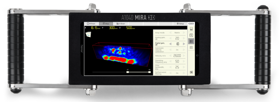
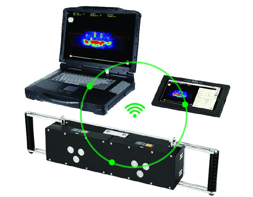

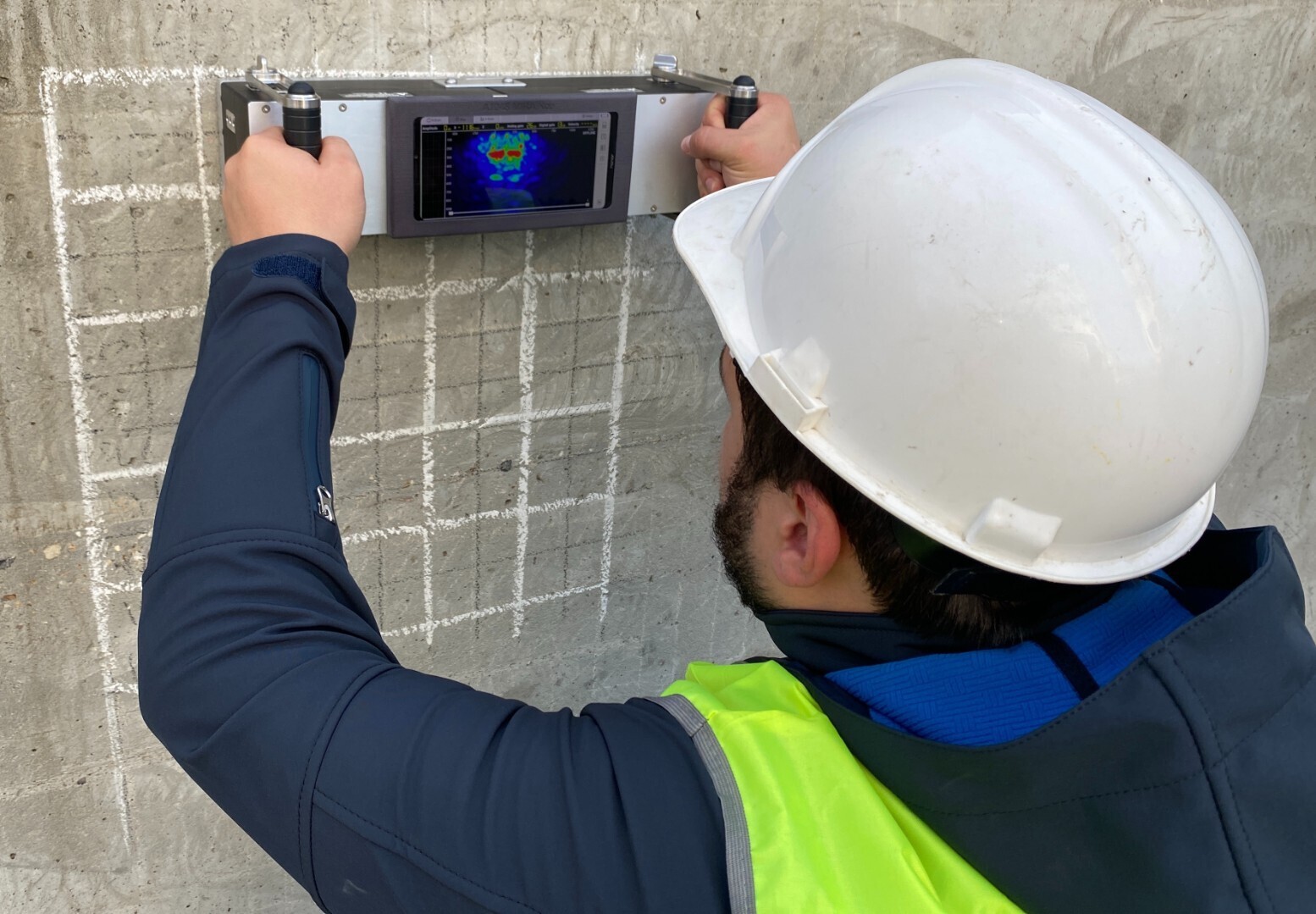
Much like modern ultrasonic flaw detectors for metal inspection, instruments for concrete testing are multi-channel phased array systems [2] whose test results are displayed as images (Fig. 1).
Figure 1: Ultrasonic tomography system for concrete testing with a 4 x 8 = 32 element array.
The decisive element of such an instrument is its ultrasonic sensors. Whereas conventional ultrasonic devices for metal testing use piezoelectric transducers coupled through a liquid medium, probes for concrete testing rely on the “dry point contact” principle (DPC) [3], in which excitation is delivered through a pin vibrating at the nominal frequency (Fig. 2).
Figure 2: Beam directivity, pulse characteristic and frequency spectrum of a DPC transducer.
The transducer construction can vary with the desired ultrasonic wave type (longitudinal or transverse), operating frequency and bandwidth. For ultrasonic imaging in concrete, broadband shear wave transducers with a center frequency of around 50 kHz are typically used [4].
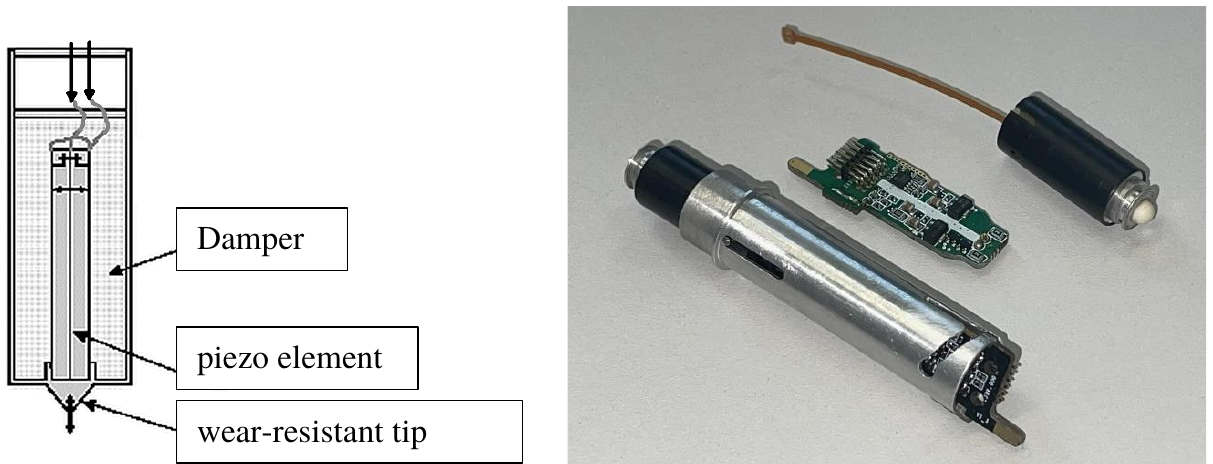
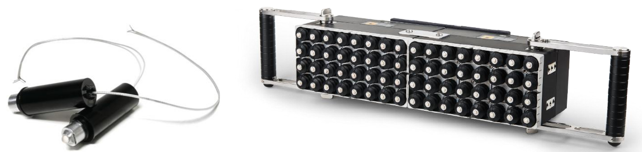
The current trend in modern DPC sensor implementation is to integrate the complete transmitter/receiver stage directly into the transducer housing (Fig. 3). Beyond its favorable low-noise electrical properties, this design makes it possible to excite and receive ultrasonic waves with every individual element of the two-dimensional matrix aperture. Inside the instrument, the spring-loaded DPC transducers are assembled into a two-dimensional matrix aperture (Fig. 4).
Figure 3: Design of an active DPC ultrasonic transducer with integrated transmitter/receiver electronics (damper, piezo element, wear-resistant tip).
Figure 4: Matrix aperture of spring-loaded dry point contact transducers.
Ultrasonic data is collected according to the “full matrix capture” (FMC) principle: the array elements act one after another as transmitters and as receivers (Fig. 5).
Figure 5: The principle of sequential excitation of the matrix aperture (3D-FMC). Red: spherical shear wave emitted by a single DPC sensor. Blue: spherical shear waves reflected back from the reinforcing bars or the material defect.
Ultrasound data coming from the two-dimensional instrument aperture of 4 x 8 DPC transducers — all 32 x 32 = 1,024 transmitter-receiver combinations — is superposed using the “total focusing method” (TFM). TFM is in turn a variant of the “synthetic aperture focusing technique” (SAFT), in which the aperture being synthesized is limited to the aperture of the phased array with alternating transmitter and receiver elements. This is how a three-dimensional image of the component volume is generated at each measuring position of the ultrasonic tomograph (Fig. 6).
Figure 6: A 3D image of a material defect at one test position of the ultrasonic device.
FMC data acquisition with a matrix aperture has another advantage: the array elements, or several aperture blocks, can be combined in any way, which expands the near field size and therefore the achievable depth of focus (Fig. 7).
Figure 7: Possible aperture combinations for 3D TFM data acquisition.
One more feature of the design of modern ultrasonic concrete tomographs deserves mention — one that may prove trend-setting for other phased array systems as well, for instance in metal testing. Reconstructing images by the TFM principle, especially when computing matrix apertures of 32 x 32 or 64 x 64 point sources, demands substantial computing power if it is to run in real time. Modern tablet PCs carry multi-core graphics processors that handle real-time 3D SAFT reconstruction of matrix aperture data without difficulty.
The data acquisition electronics is restricted to exciting and receiving the ultrasonic signals, digitizing them and transferring the raw ultrasonic data over a WiFi interface. All data processing — including digital filtering — along with image reconstruction, visualization and evaluation (reporting included) is handled by a high-performance tablet PC, or alternatively a desktop or laptop computer (Fig. 8).
Figure 8: Communication of the measurement electronics unit with different processing units.
Splitting the measurement and processing electronics and linking them wirelessly brings several advantages:
- A less expensive measurement electronics unit
- Flexible evolution of the application software (APP) without “intervention” in the measurement electronics
- Automatic benefits from each new generation of computing hardware with its improved performance
- Broad possibilities for automated recording of ultrasonic data, for example by integrating the ultrasonic device into a remotely controlled scanner unit
Separating the DAQ and processing units, communicating over a wireless link, opens the way to automated ultrasonic testing, in which the operator remotely controls not only the UT instrument but also the scanning robot (Fig. 9).
Figure 9: Automated data acquisition via a crawler robot and an inspection drone over the wireless data interface.
3. Advanced signal processing methods that extend the testing range
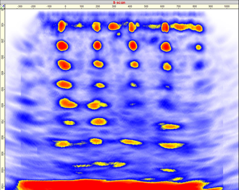
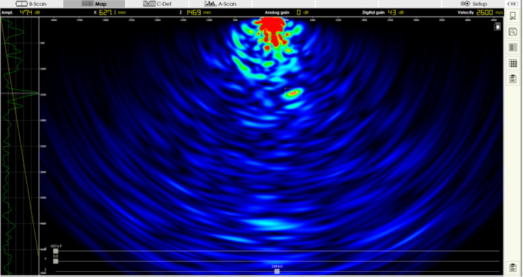
One distinctive feature of ultrasonic concrete instruments compared with other testing methods, such as ground penetrating radar, is their greater range combined with high resolution. Even on reinforced concrete, an inspection range of up to two meters can be achieved (Fig. 10).
Figure 10: B-scan display of a heavily reinforced concrete object over a range of 1.1 meter.
Still, ultrasonic testing has its physical limits too. When the material under test attenuates sound strongly — because of coarse aggregates, for instance — or when particularly thick structures such as dams with wall thicknesses of several meters are examined, an insufficient signal-to-noise ratio makes it impossible to evaluate the recorded ultrasonic signals.
If the raw ultrasonic echo signals are examined in detail, the signal noise falls into three categories:
- Coherent acoustic noise caused by ultrasonic backscattering
- Quantization noise caused by the limited resolution of the analog-to-digital conversion
- Thermal noise
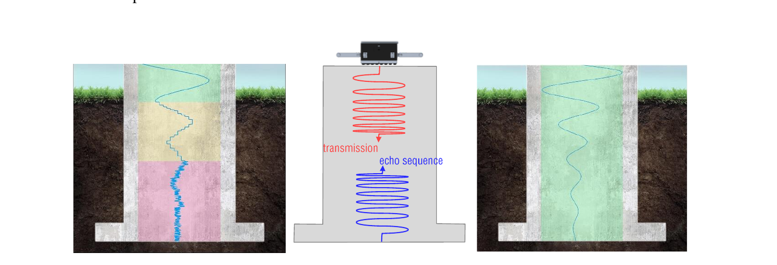
The last two noise types appear mainly on very long sound paths, where the signals are relatively weak despite high amplification values. This problem can be overcome successfully with the pulse compression technique. Instead of a short monochromatic excitation sequence, a long modulated excitation sequence excites the ultrasonic waves and is then extracted again from the received and digitized ultrasonic signal. The result is a marked improvement of the signal-to-noise ratio and of the spatial resolution (Fig. 11).
Figure 11: Schematic representation of noise types (left) and the suppression principle based on a modulated excitation sequence (right).
Decomposing the received echo signals in this way before the SAFT image reconstruction produces a denoised test result (Fig. 12).
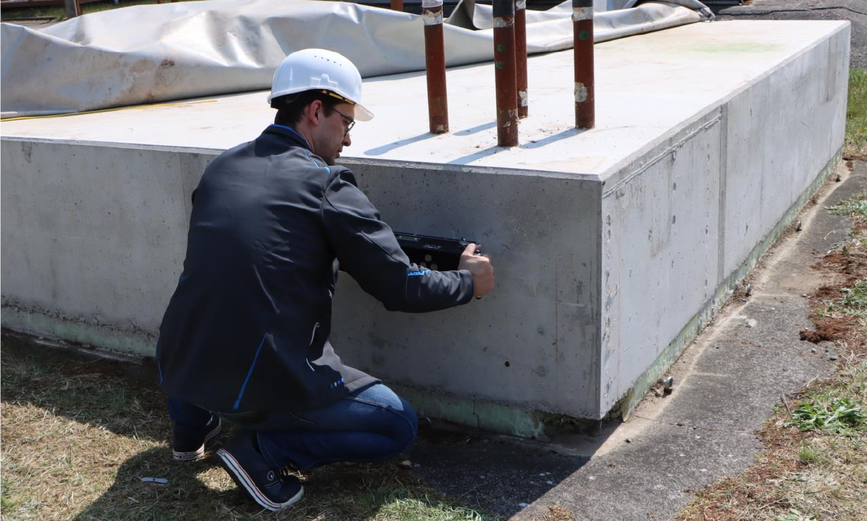
Figure 12a: Measurements on a concrete block with a wall thickness of 4 m.
Figure 12b: Test results on the 4 m concrete block, without and with the pulse compression technique.
The results in Fig. 12 were obtained on the reference object of the Federal Institute for Materials Research and Testing (BAM) at the BAM-TTS test ground in Horstwalde, Brandenburg.
4. Types of 3D visualization and result presentation
Moving from the line array principle to the matrix array principle brings new options for visualizing ultrasonic test results. The “elementary” data set at a test position is a three-dimensional volume data set for each recording, with better spatial resolution than line-array devices deliver — thanks to the implementation of the 3D TFM principle. Naturally this calls for a more demanding hardware implementation, such as a fully parallel arrangement of the ultrasound channels and computationally intensive 3D SAFT reconstruction.
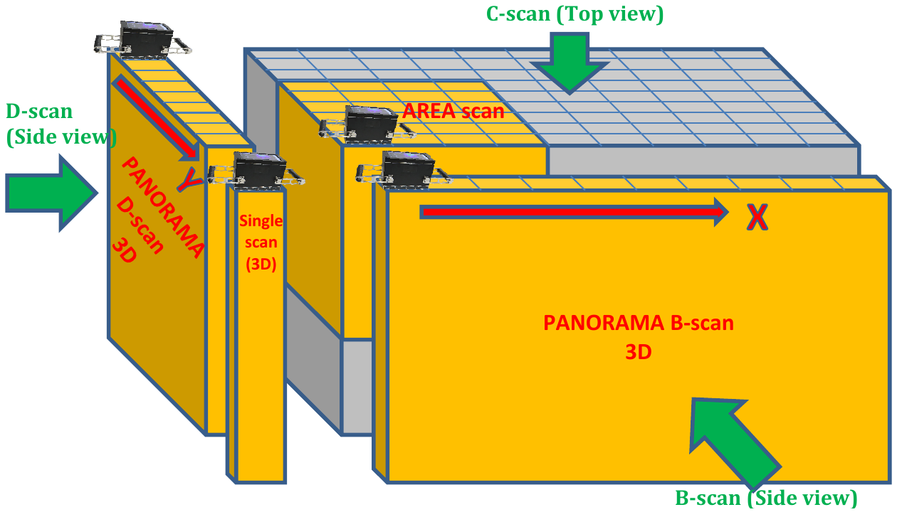
With any type of component scanning using equidistant measuring points in both the X and Y directions, three-dimensional data sets (Panorama B-scan and Panorama D-scan) are produced (Fig. 13), visualized so that three side views — B, C and D scans — are shown respectively. Recording in two-dimensional MAP mode along both scan axes X and Y produces volume data sets (area scans) of any size, whose on-screen display requires appropriate tools such as zooming and scrolling.
Figure 13: Volume display modes for visualizing the ultrasound data (single 3D scan, Panorama B-scan, D-scan, C-scan top view, AREA scan).
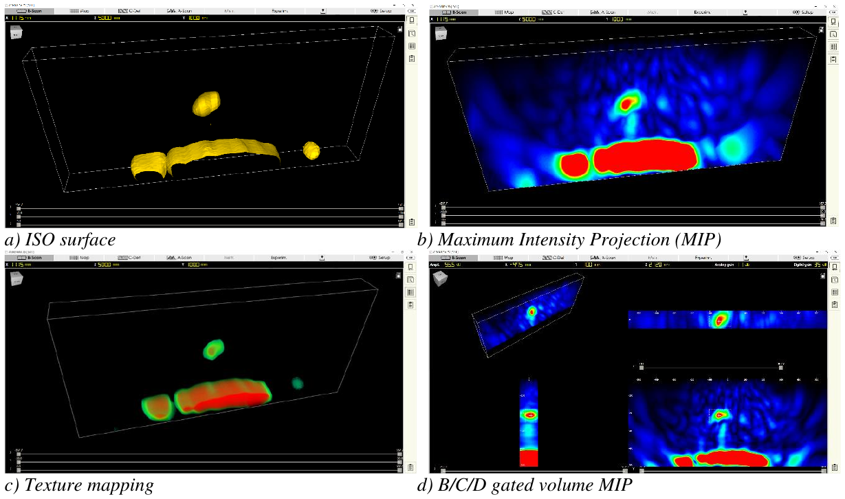
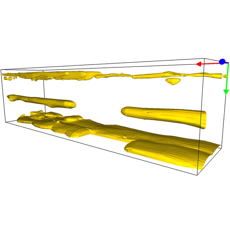
Depending on the application, the voxel data itself can be rendered in different visualization modes (Fig. 14): ISO surface, Maximum Intensity Projection (MIP), texture mapping, and B/C/D gated volume MIP.
Figure 14: 3D rendering modes for the reconstructed volume data: a) ISO surface, b) Maximum Intensity Projection (MIP), c) texture mapping, d) B/C/D gated volume MIP.
Modern 3D tomographs ship with dedicated post-processing software — such as MIRA NEO software — that brings these rendering modes together for volume analysis, defect sizing and reporting on a desktop computer.
5. Evaluating crack depth
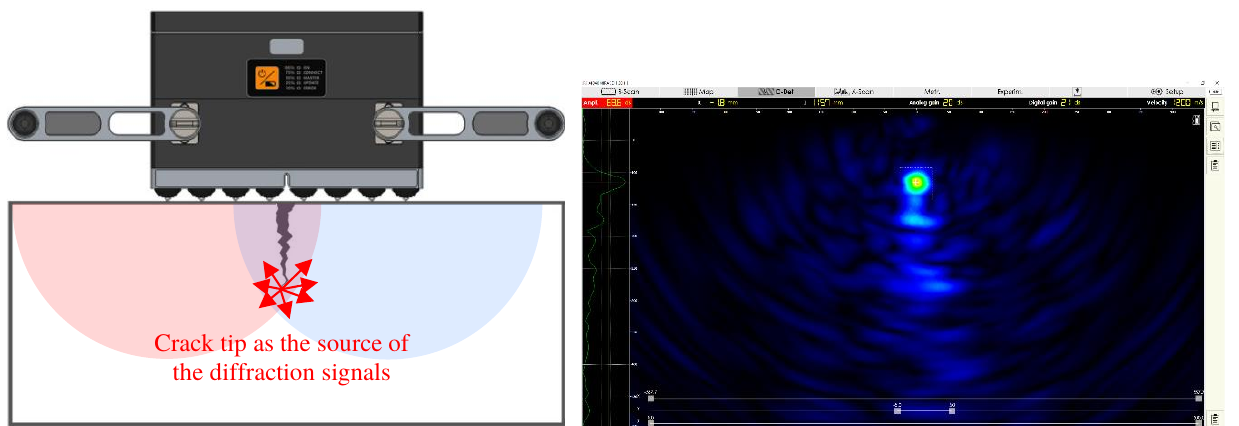
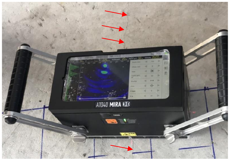
Another notable strength of the matrix aperture with its extremely small single array elements is a very broad beam directivity characteristic. Among other things, it allows diffraction signals to be captured from unfavorably oriented material flaws — for example the tip of an outwardly open crack. That makes it possible to determine the depth of such defects without insonifying them “frontally”.
Carrying out such a measurement requires the number of DPC sensors on both sides of the open crack to be equal, and the crack depth must not exceed the overall aperture size of the device (Fig. 15).
Figure 15a: Arrangement of the instrument aperture relative to the crack (left) in the crack depth measurement mode of the ultrasonic tomograph (right). The crack tip acts as the source of the diffraction signals.
Figure 15b: Measuring the depth of a natural crack in a structure.
6. Summary and outlook
This article has reviewed current trends in the implementation and application of imaging ultrasonic testing systems for non-destructive concrete inspection. At their core are matrix apertures built from active DPC ultrasonic transducers, and three-dimensional FMC/TFM methods for tomographic imaging. This sensor design also permits pulse compression techniques when exciting the ultrasonic waves, significantly extending the achievable inspection range to several meters.
The shift from the conventional line array principle to matrix apertures delivers three-dimensional tomographic imaging with improved spatial resolution at every position of the ultrasonic tomograph, together with special functions for quantitative defect assessment in the near field of the ultrasonic sensor system — such as evaluating crack depth. The full conference versions of this material are available as references [5] and [6].
7. Delta Test Technologies and 3D-FMC instruments
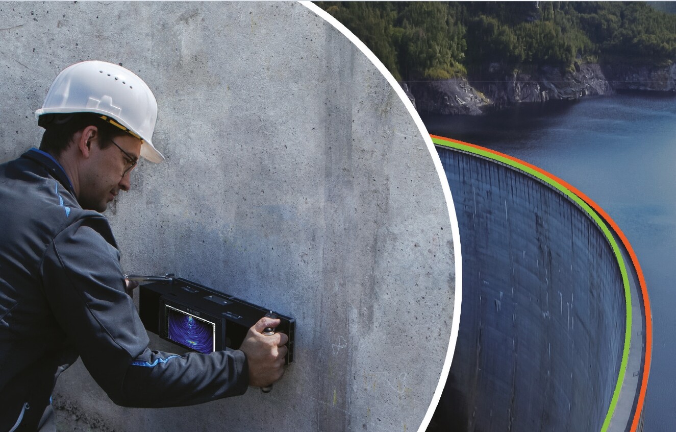
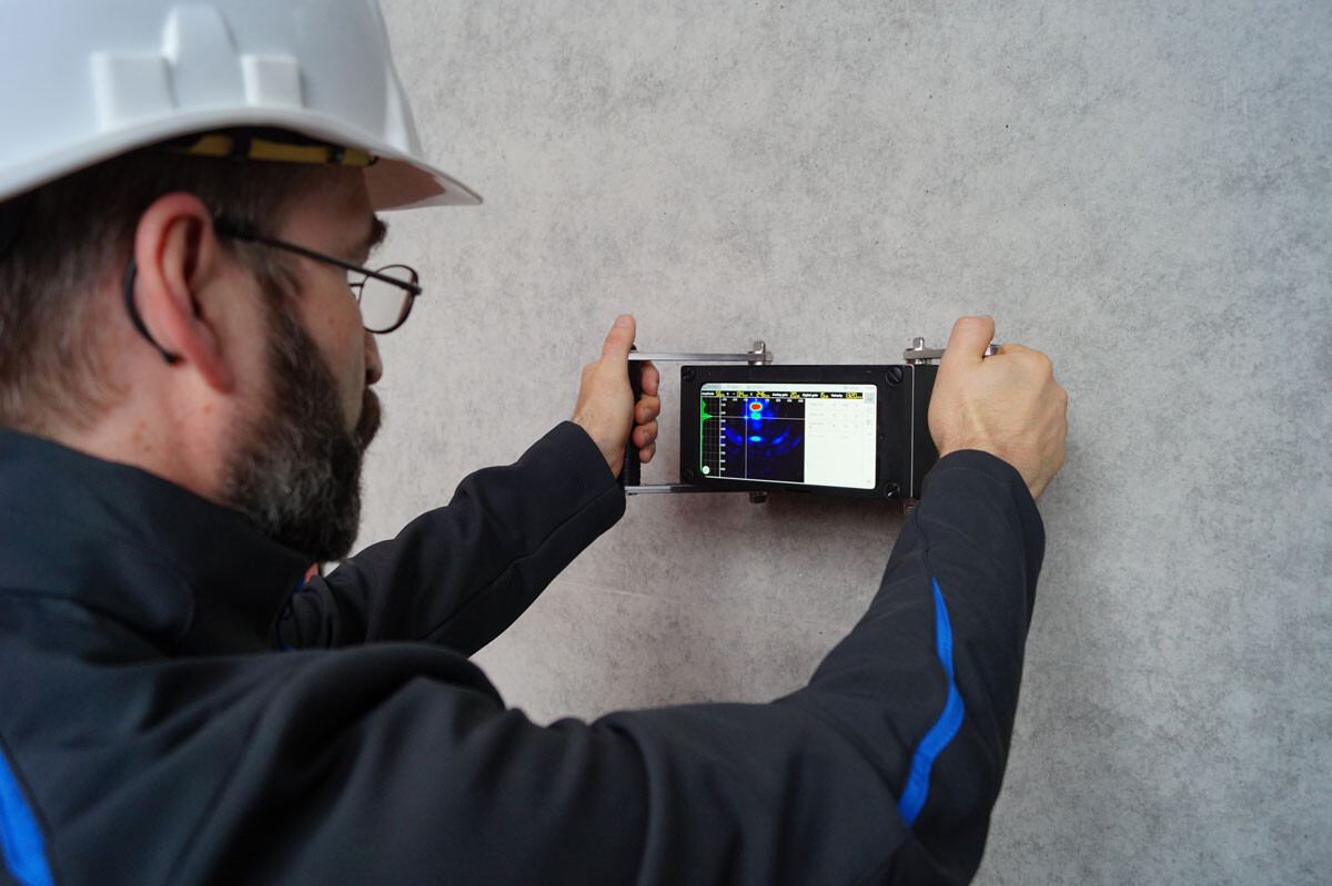
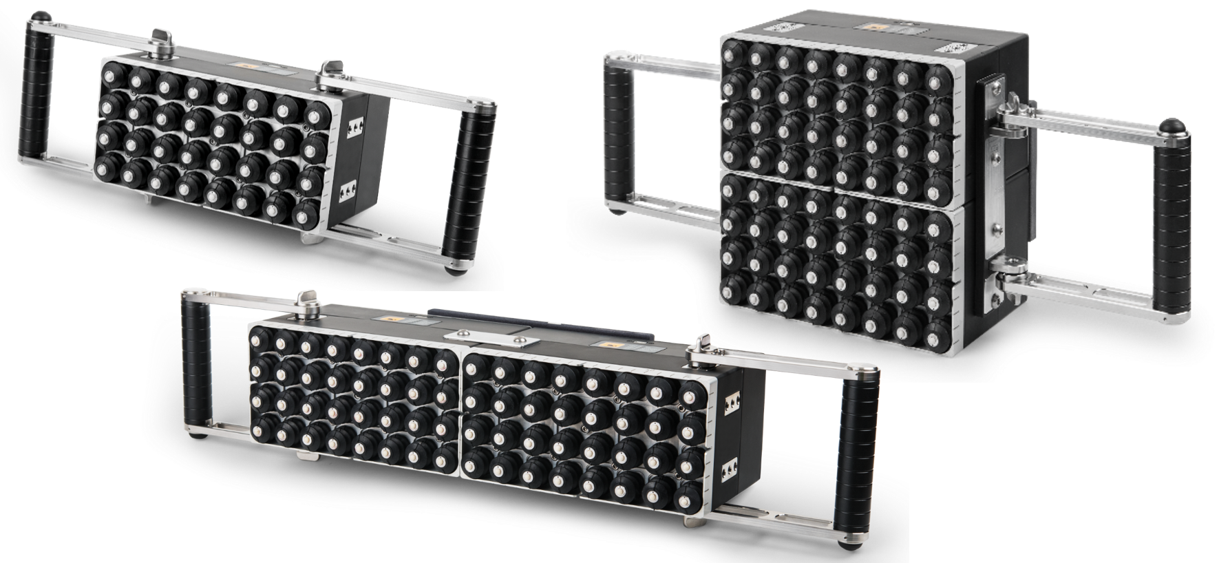
The methods described in this article are not laboratory concepts. They are implemented in the ultrasonic tomography instruments that Delta Test Technologies supplies for ultrasonic concrete testing. The A1040 MIRA 3D family works with a matrix aperture of active DPC transducers, 3D-FMC data acquisition and real-time TFM reconstruction on a wirelessly connected processing unit. The base instrument uses the 4 x 8 aperture of 32 elements described in this article, and the A1040 MIRA 3D Pro extends the aperture to 64 elements and more. The pulse compression mode for thick structures is implemented as the E-Boosting function, and the crack depth measurement mode described above is available on the instrument.
The reason instrument manufacturers develop both the transducers and the reconstruction software in-house is the same reason this article covers both: the image quality of ultrasonic tomography depends on the entire chain — from the contact point of the sensor to the rendering of the reconstructed volume.
Frequently Asked Questions
What is 3D-FMC in ultrasonic concrete testing?
3D-FMC stands for three-dimensional Full Matrix Capture. Every element of the two-dimensional matrix aperture transmits in turn while all elements receive. With a 4 x 8 aperture that produces 32 x 32 = 1,024 transmitter-receiver combinations, which the Total Focusing Method (TFM) then superposes into a three-dimensional image of the component volume at each measuring position.
How deep can ultrasonic tomography see in concrete?
With standard excitation, inspection ranges of up to two meters are attainable even in reinforced concrete. Pulse compression — where a long modulated excitation sequence replaces the short monochromatic pulse — stretches the range to several meters. The results shown here were verified on a concrete block with a wall thickness of 4 m at the BAM test site in Horstwalde. According to current instrument specifications, the A1040 MIRA 3D reaches a maximum penetration depth of up to 3 m in reinforced concrete, and the A1040 MIRA 3D Pro exceeds 4 m with the E-Boosting technique.
Why do concrete testing probes not need couplant gel?
The probes work on the dry point contact (DPC) principle. A wear-resistant pin vibrating at the nominal frequency injects the ultrasound into the concrete through a single contact point, so no liquid coupling medium is needed. The spring-loaded transducers conform to rough concrete surfaces.
What is the difference between TFM and SAFT?
TFM is a variant of the Synthetic Aperture Focusing Technique (SAFT) in which the aperture to be synthesized is restricted to the aperture of the transducer array, with alternating transmitter and receiver elements. In modern concrete tomographs, 3D TFM reconstruction runs in real time on the graphics processor of a tablet PC.
Can ultrasonic tomography measure the depth of a crack?
Yes — for outwardly open cracks. The broad beam directivity of the small matrix array elements picks up diffraction signals from the crack tip, so the crack does not have to be insonified frontally. The measurement needs an equal number of DPC sensors on either side of the crack, and the crack depth must not exceed the overall aperture size of the device. This measurement is implemented as a dedicated crack depth mode in the A1040 MIRA 3D ultrasonic tomograph, which evaluates the depth of open surface cracks with one-side access directly on the instrument.
What is the advantage of ultrasound over ground penetrating radar for concrete?
Greater range with high resolution, and higher sensitivity to material defects (cracks, honeycombs, cavities, grouting defects). GPR is a widely used method for locating objects in concrete, but the ultrasonic instruments described here reach up to several meters in reinforced concrete while retaining the sensitivity and spatial resolution needed for defect detection and evaluation.
References
[1] V.N. Kozlov, A.A. Samokrutov, V.G. Shevaldykin. Thickness measurements and flaw detection in concrete using ultrasonic echo method. Nondestructive Testing and Evaluation 13(2): 73-84, January 1997.
[2] V. Shevaldykin, A. Samokrutov, V. Kozlov. Ultrasonic low-frequency short-pulse transducers with dry point contact. Development and application. International Symposium Non-Destructive Testing in Civil Engineering (NDT-CE), 16-19 September 2003. Journal of Civil Engineering and Management, 2013, 19(6): 775-786.
[3] A.O. Haza, C.G. Petersen, A. Samokrutov. Three-Dimensional Imaging of Concrete Structures Using Ultrasonic Shear Waves. German Instruments SA, Denmark, 2011.
[4] A. Bishko, A.A. Samokrutov, V.G. Shevaldykin. Ultrasonic echo-pulse tomography of concrete using shear waves low-frequency phased antenna arrays. Proceedings of the 17th World Conference on Non-Destructive Testing, 2008.
[5] A. Bulavinov, R. Pinchuk, A. Samokrutov, V. Shevaldykin. New trends in the ultrasonic imaging of concrete structures by means of 3D-FMC technology. NDT-CE 2022, International Symposium on Non-Destructive Testing in Civil Engineering, Zurich, Switzerland, August 2022. DOI 10.58286/27285.
[6] A. Bulavinov, R. Pinchuk, A. Samokrutov, V. Shevaldykin. Advanced tomographic imaging techniques for quality assessment of concrete structures by means of ultrasound. NDE NucCon 2023, International Conference on Non-destructive Evaluation of Concrete in Nuclear Applications, Espoo, Finland, January 2023.