
Dry-Point-Contact Ultrasonic Transducers for Non-Destructive Material Testing
Dry-point-contact (DPC) ultrasonic transducers feed sound into a test piece through small, hard tips that touch the surface at a few discrete points — with no gel, water, or oil in between. That design decision makes it possible to generate low-frequency ultrasound that keeps working on materials where liquid-coupled high-frequency probes fail: concrete, stone, fibre-reinforced composites, wood, and metal that is rough, coated, or hot.
This article explains how DPC transducers are constructed, how longitudinal and shear waves are formed at a point contact, how single elements grow into arrays, and how SAFT and TFM convert array data into images. The same dry-contact principle underlies modern couplant-free instruments for concrete tomography, pulse-velocity testing, and guided-wave inspection. If you inspect concrete, rock, or difficult surfaces, this is the physics behind the readings.
What this article covers:
- The design and physics of DPC transducers: operating frequency, damping, and beam directivity
- The path from single transducers to passive and active arrays, and on to SAFT and TFM imaging
- Couplant-free inspection in the field, and concrete tasks: thickness, rebar, voids, crack depth, and strength by UPVT
- Guided-wave inspection of pipes, poles, and other extended structures
This material is adapted from the technical paper presented at the 11th Journées COFREND 2026, the congress of the French Confederation for Non-Destructive Testing (COFREND), held at the Lyon Convention Centre on 19 to 21 May 2026 under the theme “Voir aujourd’hui, Prévoir demain.” It has been reworked by the Delta Test Technologies team for this blog.
Abstract
This article reviews the physical principles, design features, and field applications of low-frequency piezoelectric dry-point-contact (DPC) transducers in ultrasonic non-destructive testing. We show how discrete mechanical contact delivers ultrasonic energy efficiently with no couplant, which makes DPC probes particularly well suited to coarse-grained and porous materials. We examine how the wave field forms around the contact point, how longitudinal and shear waves are excited, and what the beam directivity patterns imply for the spatial sensitivity of the probe. We then look at practical uses — inspection of concrete and rock, and ultrasonic tomographic techniques built on SAFT and TFM algorithms — and discuss the strengths, the limitations, and the likely future development of the technology.
Keywords: ultrasonic testing, dry-point-contact, DPC, SAFT, TFM, directivity pattern.
1. Introduction
Ultrasonic testing (UT) ranks among the principal diagnostic methods for evaluating materials and structures, thanks to its high sensitivity to internal defects such as cracks, voids, delaminations, and inclusions. The method excites ultrasonic waves inside the inspected object and then analyses how they propagate, reflect, and scatter.
Conventional UT usually relies on contact piezoelectric transducers that need a liquid couplant layer — water, gel, or oil — to get acoustic energy into the test object efficiently. While this approach works very well on metals and other homogeneous materials, it runs into serious limitations in a number of practical applications.
Liquid couplants are particularly difficult or impossible to use in field inspection of porous, capillary-active materials such as concrete, stone, glass-fibre-reinforced composites, and wood. For such conditions, low-frequency dry-point-contact (DPC) transducers offer a promising alternative: they transmit low-frequency ultrasonic waves through several localized contact zones and need no liquid couplant at all.
DPC transducers sit midway between conventional piezoelectric contact probes and air-coupled ultrasonic systems. They combine fairly high acoustic transmission efficiency with low sensitivity to surface condition, and they operate in the low-frequency ultrasonic band of roughly 20 to 400 kHz.
The goal of this article is to give a systematic overview of the physical principles and engineering aspects of DPC transducers, with the main focus on practical applications and signal-processing techniques.
2. Design and Physical Principles of DPC Transducers
2.1 Design of DPC Transducers
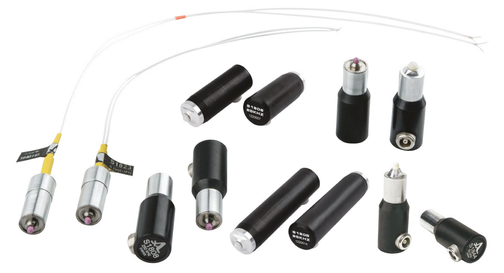
The defining characteristic of DPC transducers is how the acoustic coupling is formed. Instead of the continuous contact surface of a conventional piezoelectric probe, DPC transducers use discrete point-contact elements — or arrays of such elements.
These contact elements (tips) make localized mechanical contact with the surface of the inspected object. The real contact area is far smaller than the geometric contact area, yet the high local contact pressure and the solid mechanical coupling between tip and surface ensure that ultrasonic vibrations are transmitted into the test object effectively.
Another major difference from conventional piezoelectric probes is the size of the tip that carries vibrations from the piezoelectric element to the acoustic contact point: it is far smaller than the ultrasonic wavelength. Because of these acoustically small dimensions, the tip acts as a lumped mechanical body and vibrates with practically no internal deformation.
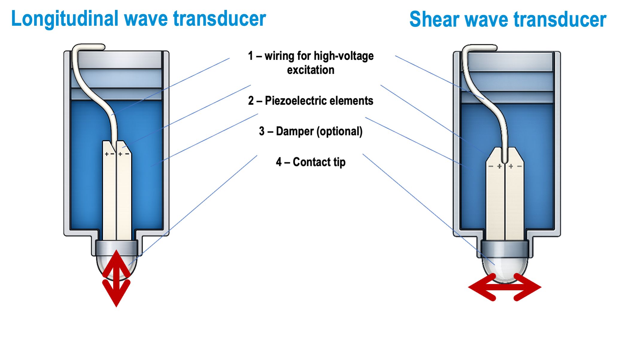
The schematic design of a longitudinal-wave DPC transducer is shown below. The transducer produces normal stresses at the contact point with the solid surface. For clarity, the piezoelectric element is drawn as a two-layer structure, though more layers can be used. The “+” and “−” symbols denote the polarization directions of the piezoelectric plates; with this polarization arrangement, the piezoelectric element performs longitudinal expansion–contraction oscillations.
The arrows show the vibration directions of the contact tip. Changing the polarization configuration of the two-layer piezoelectric element switches the vibration mode of the contact tip from longitudinal (normal) to shear oscillations.
2.2 Operating Frequencies and Spectral Characteristics of DPC Transducers
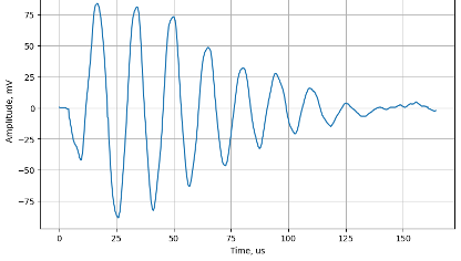
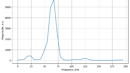
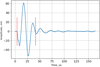
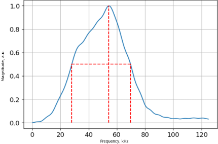
Depending on the design and dimensions of the piezoelectric elements, DPC transducers operate across a frequency band from 20 to 400 kHz. Whether the transducer is damped also determines its frequency response.
Undamped, narrow-band transducers are the right choice for velocity measurements. Damped transducers emit short, broadband pulses instead, which delivers the resolution required for pulse-echo imaging. Pulse and frequency responses of undamped and damped DPC transducers are shown below.
The damping element is usually made from a liquid composite material with high ultrasonic attenuation and covers the entire free surface of the piezoelectric element.
2.3 Directivity Patterns of DPC Transducers
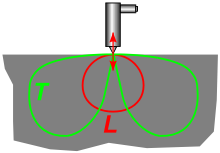
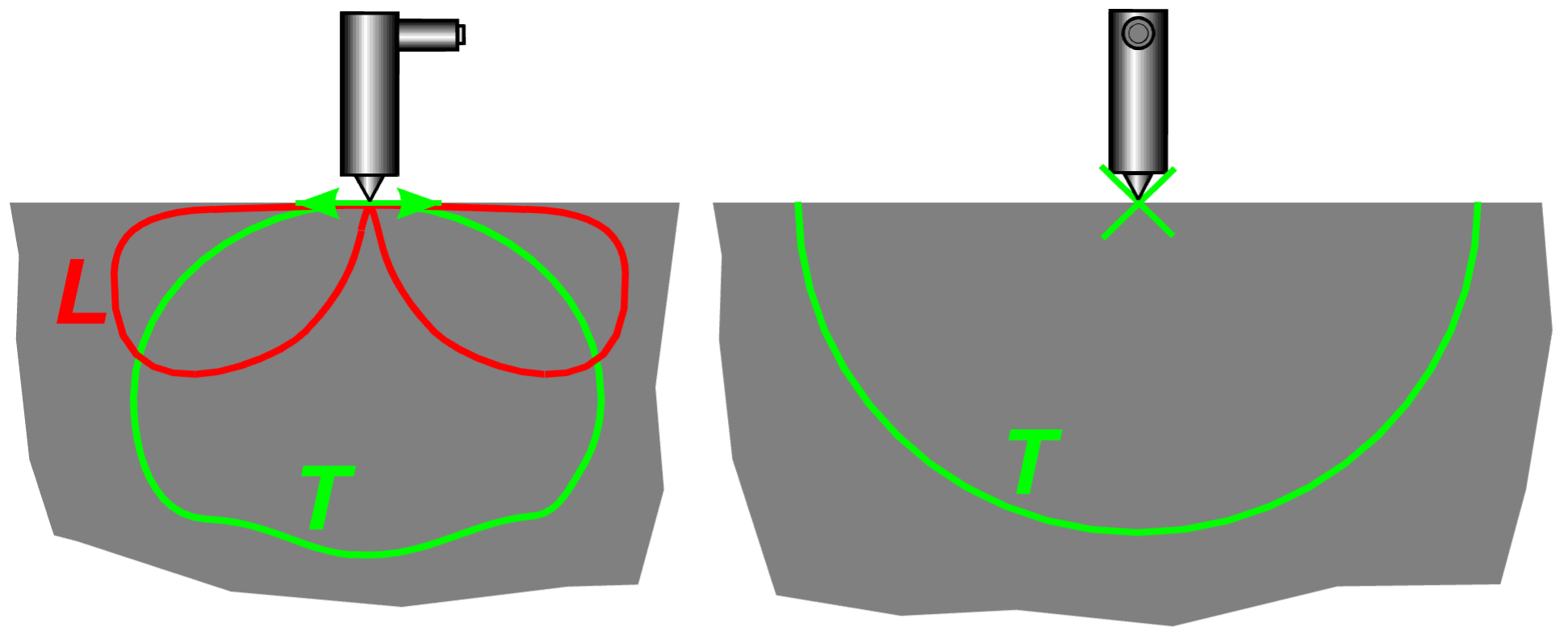
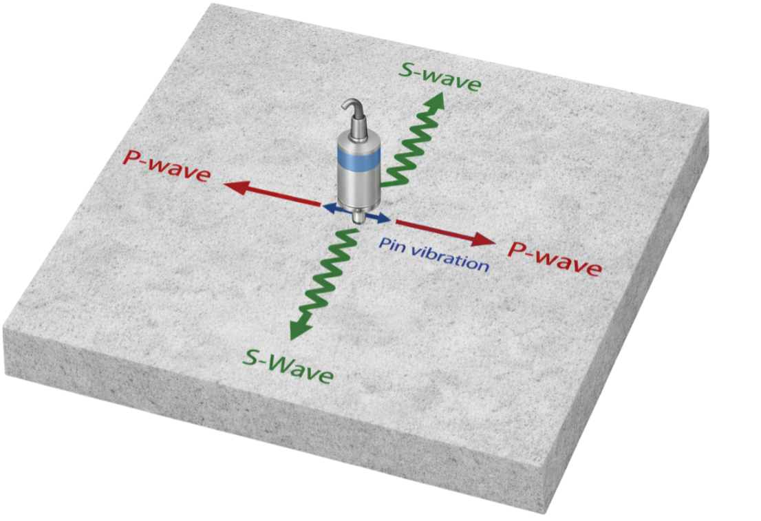
The directivity pattern describes how transmitted and received ultrasonic energy is distributed in space and is one of the key characteristics of any ultrasonic transducer. Due to the low operating frequency and the small effective aperture of DPC transducers, their radiation patterns are typically broad.
A transducer whose contact tip oscillates longitudinally generates and receives longitudinal bulk waves propagating perpendicular to the surface of the half-space. A transducer whose contact tip oscillates in shear generates and receives shear bulk waves travelling in the normal direction.
Because of the point acoustic contact, every transducer inevitably excites and receives — alongside the dominant wave mode — additional ultrasonic wave types propagating at specific angles to the surface of the half-space.
Surface waves of various types spread along the surface from the contact point in different directions. A transducer with a longitudinally oscillating tip acts as an omnidirectional source of Rayleigh waves. A transducer with a shear-oscillating tip produces longitudinal subsurface (head) waves and Rayleigh waves in the direction of the displacement vector. In the direction perpendicular to the displacement vector, the same transducer excites horizontally polarized shear waves (SH waves).
These properties of shear-oscillation DPC transducers allow longitudinal and shear wave velocities in materials to be measured with indirect through-transmission techniques.
3. Multi-Element DPC Systems (Arrays) and Signal Processing Methods
3.1 Transition from Single Transducers to Arrays
Single DPC transducers, with their point-like aperture, excite and receive low-frequency ultrasonic waves efficiently. Still, they remain limited for flaw detection because of several inherent drawbacks:
- no spatial selectivity;
- difficulty locating defects inside the inspected volume;
- ambiguity when interpreting the signals.
Moving from single-element probes to multi-element array systems fundamentally expands what ultrasonic measurements can do.
3.2 Passive and Active Arrays Based on DPC Transducers
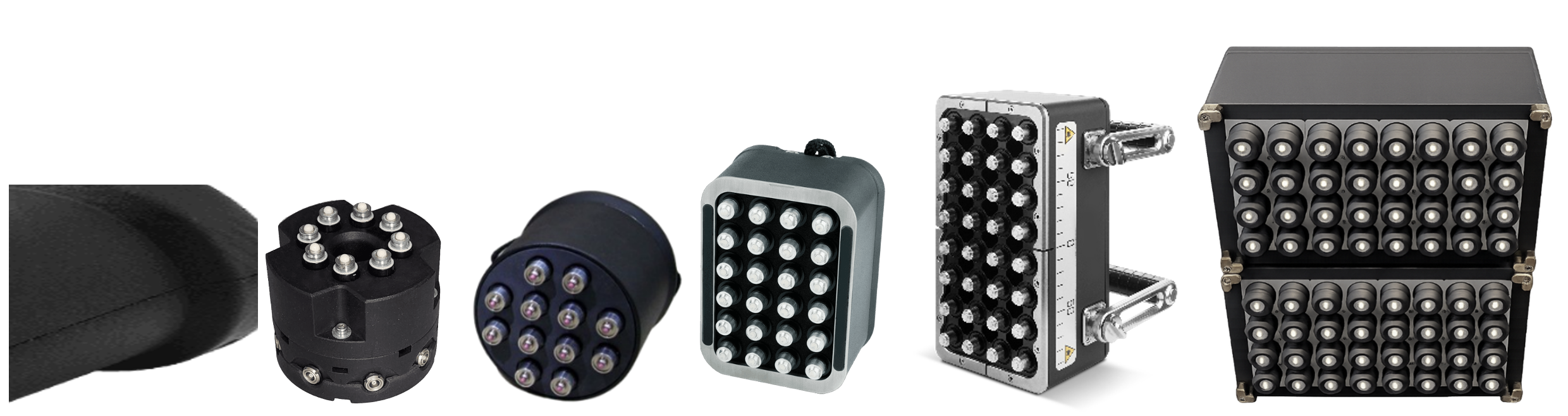
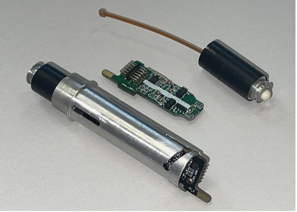
To extend the inspection range, DPC transducers are grouped into arrays that produce a more directional beam. Each element is mounted on a spring inside the housing, which keeps the contact pressure stable even on uneven surfaces.
Such arrays are implemented either as passive systems — without built-in transmitting and receiving electronics — or as active systems with transmitter and receiver circuitry integrated directly into the DPC transducer housing.
In active systems, the signal-to-noise ratio of the received ultrasonic echo signals is considerably improved. This is particularly important for synthetic-aperture imaging techniques, where it makes it possible to reconstruct tomographic images with substantially higher detection capability and spatial resolution.
3.3 Features of DPC Array Applications
A DPC array is a set of independent dry-point-contact transducers. Each can work either in sync with the other elements, as part of a common physical aperture sharing one acoustic channel, or independently in transmit–receive mode, as an element of a synthetic aperture.
The second mode requires multichannel electronics to collect pitch-catch data for every possible transmitter–receiver combination. This yields the complete synthetic-aperture dataset, known as Full Matrix Capture (FMC).
Compared with conventional piezoelectric phased arrays, DPC arrays have several distinctive characteristics:
- Low operating frequency and therefore large ultrasonic wavelength. This strongly limits what conventional phase-based beam steering can achieve.
- Extremely broad directivity patterns of the individual elements. Each element behaves roughly like a point source and simultaneously emits multiple types of bulk and surface waves.
With DPC arrays, therefore, the emphasis moves away from steering the beam and toward signal processing and image reconstruction.
3.4 Synthetic Aperture Focusing Technique (SAFT)
The Synthetic Aperture Focusing Technique (SAFT) is not the main subject of this article, so only the aspects most relevant to DPC arrays are briefly covered.
SAFT coherently sums signals acquired at different transmitter and receiver positions. In effect, it reconstructs the echo as though it originated from a single point inside the part.
For DPC transducers, SAFT works especially well because it:
- takes full advantage of the broad directivity patterns of the transducers;
- improves spatial resolution;
- effectively suppresses the stochastic noise caused by the structural heterogeneity of the material.
In practice, SAFT provides:
- localization of reflecting objects;
- better image contrast.
3.5 Total Focusing Method (TFM)
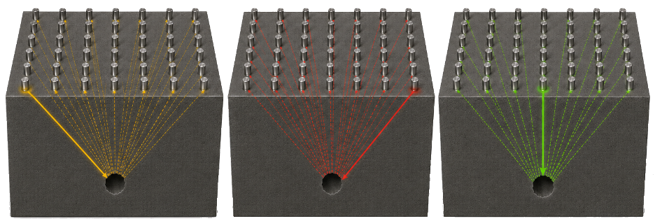
The Total Focusing Method (TFM) develops the Synthetic Aperture Focusing Technique further and uses the complete Full Matrix Capture (FMC) dataset recorded with linear and matrix array apertures.
For every point of the reconstructed image, the following operations are carried out:
- computing the ultrasonic travel time from each transmitting element to the image point and then on to each receiving element;
- coherently summing the corresponding signals with the appropriate delay laws;
- for heterogeneous propagation media, applying correlation-based signal superposition techniques to improve image quality and suppress incoherent noise.
4. Application Areas of DPC Transducers and DPC Transducer Arrays
DPC transducers and arrays built from them — like other ultrasonic piezoelectric probes — serve both for studying the physical properties of materials and for flaw detection. Their capabilities depend on the inspection task and on the material’s properties.
A defining trait of DPC transducers is that, by design, they generate low-frequency ultrasonic waves, making them well suited to structurally heterogeneous materials with high ultrasonic attenuation. In particular, they maintain stable acoustic coupling under the following conditions:
- high surface roughness and irregularity;
- the presence of surface coatings;
- high surface curvature combined with limited probe aperture dimensions;
- elevated or reduced operating temperatures.
Depending on the application, two principal operating modes are used:
- through-transmission mode — for assessing the mechanical properties of the medium, including strength evaluation;
- pulse-echo mode — for locating material discontinuities and detecting embedded metallic structural elements.
4.1 Inspection of Materials without Liquid Acoustic Coupling
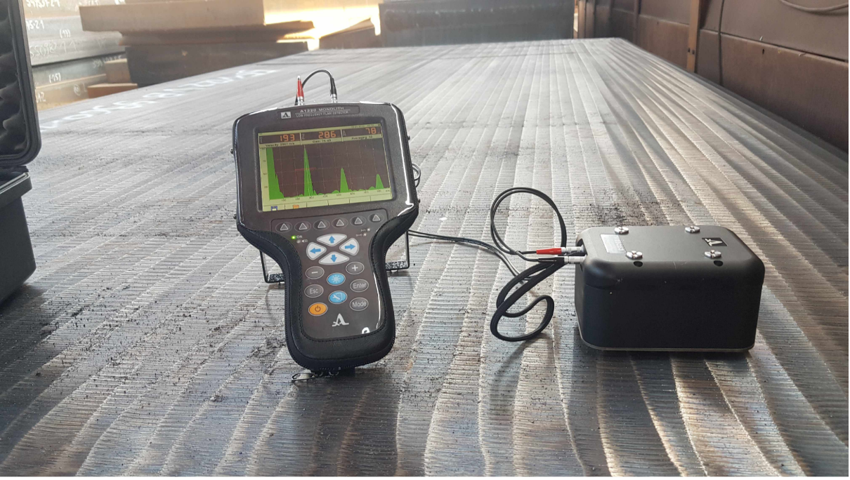
DPC transducers prove their worth wherever a liquid couplant is impractical or would distort the measurement.
Typical applications include:
- non-destructive testing of heterogeneous and highly scattering materials (concrete and rock, GFRP, wood);
- in-situ inspection of civil engineering structures, including vertical and overhead surfaces;
- inspection of porous and hygroscopic materials, such as carbon electrodes;
- inspection of objects with contaminated, rough, or abrasive surfaces;
- operation at low and high temperatures.
Eliminating the couplant is not only a matter of convenience — it also makes measurements more reproducible:
- there is no variable intermediate layer between the transducer and the test object;
- the signal depends less on couplant layer thickness;
- serial measurements become more repeatable and reproducible.
At the same time, several additional factors become critical:
- stability of the contact pressure;
- monitoring the condition and wear of the contact tips, because their dimensions directly influence the transmission and reception delay times.
One example is thickness measurement of a heavy steel plate at elevated temperature using a dual-element DPC array operating at 150 kHz.
4.2 Inspection of Concrete and Reinforced Concrete Structures
Concrete is one of the most characteristic fields for DPC transducers. Its structure comprises:
- coarse aggregates (gravel, crushed stone);
- the cement matrix;
- reinforcement elements such as steel rebars and tendon ducts.
From the standpoint of ultrasonic wave propagation, concrete is a strongly scattering, structurally heterogeneous medium. When the ultrasonic wavelength approaches the characteristic aggregate size:
- multiple scattering occurs;
- the ultrasonic signal rapidly loses coherence.
Under these conditions, high-frequency ultrasonic inspection methods stop being effective, and low-frequency techniques typical of DPC systems are used instead.
The typical concrete inspection tasks are covered below. Delta Test Technologies offers a dedicated line of ultrasonic concrete testing equipment built around these principles.
4.2.1 Thickness Measurement of Structures
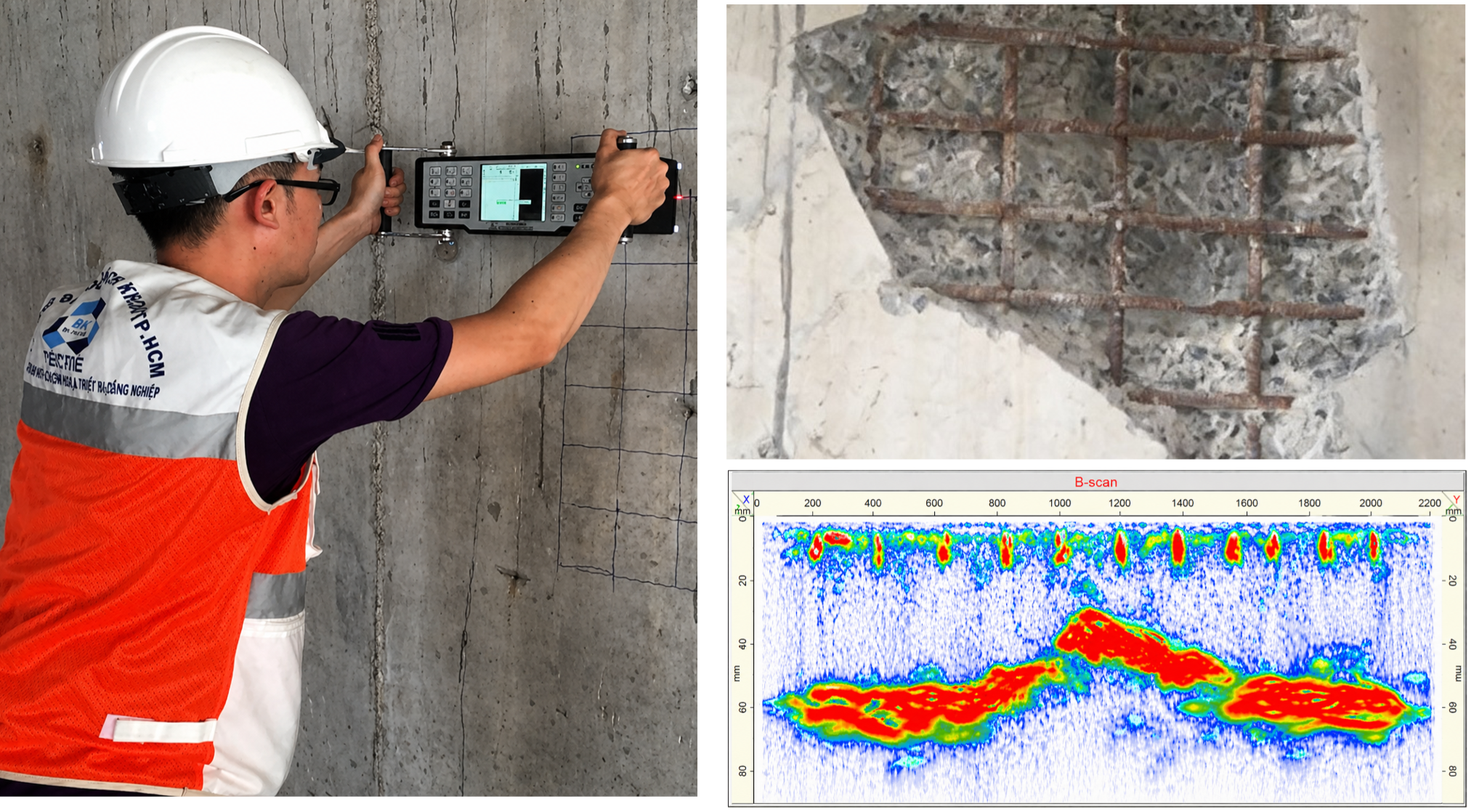
With single-sided access, measuring the ultrasonic wave travel time in pulse-echo mode allows the thickness to be determined. Accurate thickness evaluation depends critically on correct calibration of the ultrasonic wave velocity, which should preferably be performed on a region of the test object whose thickness is known.
When the object thickness is unknown and only one side is accessible, modern ultrasonic instruments can calibrate the ultrasonic velocity automatically using surface-wave-based techniques.
Back-wall spalling in a concrete structure, for instance, can be detected with one-sided ultrasonic thickness measurements. For pulse-echo thickness gauging in dry contact, instruments such as the A1220 MONOLITH 3D ultrasonic pulse-echo flaw detector implement this mode.
4.2.2 Localization of Metallic Structural Elements (Reinforcement Bars)
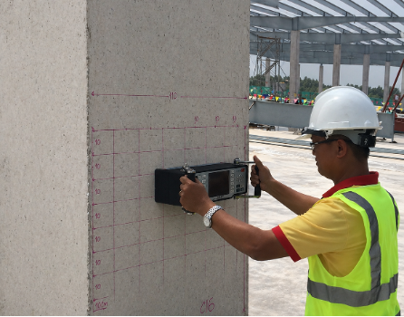
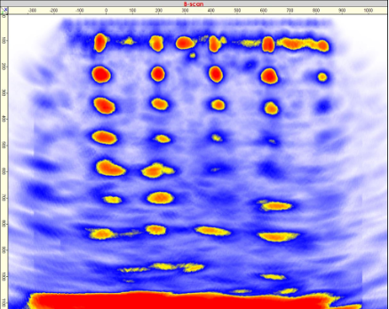
Although electromagnetic methods are often more sensitive to metallic elements in near-surface concrete layers, ultrasonic tomography is also a highly informative technique for this purpose — particularly in massive reinforced concrete structures with multilayer reinforcement. Multilayer reinforcement has been detected, for example, in a massive concrete structure 1.1 m thick.
Shear-wave tomographic imaging of this kind is implemented in instruments such as the A1040 MIRA 3D ultrasonic tomograph.
4.2.3 Detection of Voids and Honeycombing
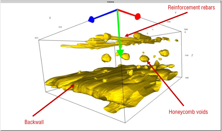
Voids produce strong ultrasonic reflections because of the large acoustic-impedance contrast between the defect and the surrounding material. However, multiple scattering effects and the relatively low reflectivity of certain discontinuities often make the received signals blurred and hard to interpret directly. In such cases, spatial signal-processing techniques such as the Synthetic Aperture Focusing Technique (SAFT) are required to improve defect localization and image quality.
4.2.4 Crack Depth Measurement
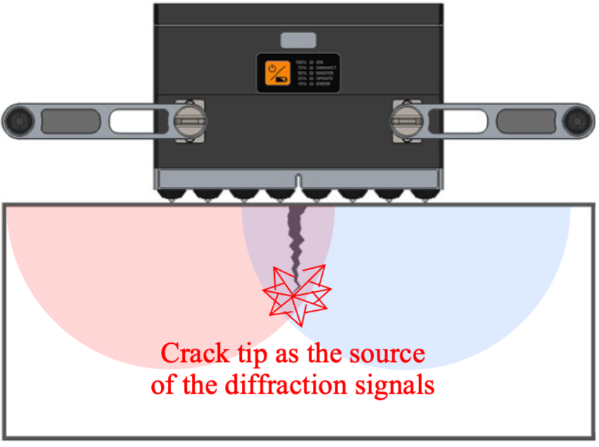

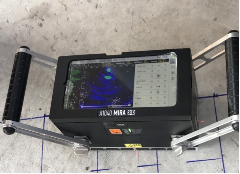
Cracks act as acoustic reflectors with pronounced directivity, so shear-wave transducers detect them most effectively. In DPC transducers, shear waves are generated naturally as a result of the point-contact excitation mechanism — a significant advantage of this technology.
The depth of surface-opening cracks (perpendicular to the surface) can be measured with a matrix DPC array using the diffraction signals coming from the crack tip.
4.2.5 Evaluation of Concrete Strength Using UPVT
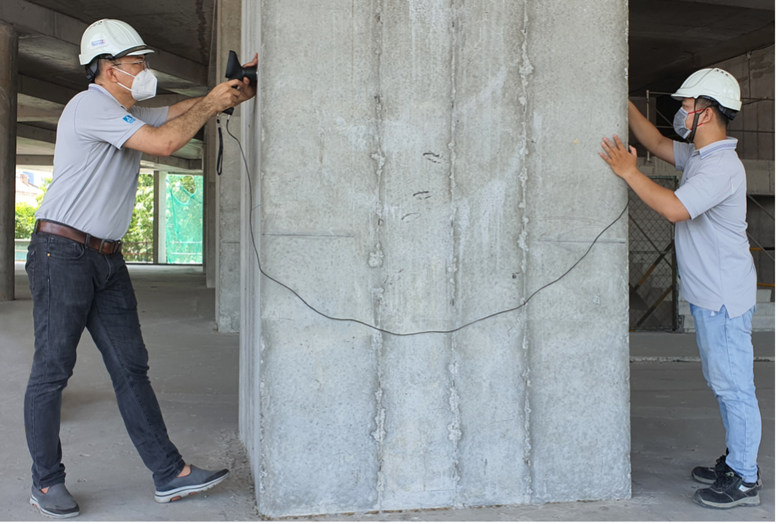
The Ultrasonic Pulse Velocity Test (UPVT) method measures the propagation velocity of ultrasonic waves in concrete to indirectly assess its mechanical and structural properties. It makes it possible to detect defects, cracks, low-density zones, and material heterogeneities, and it also gives an integral assessment of concrete quality. For quantitative strength evaluation, UPVT results are normally calibrated against reference samples of known compressive strength or correlated with destructive testing data.
Through-transmission testing of a massive concrete structure has been performed with an instrument using two DPC arrays operating at 100 kHz and transmitting and receiving longitudinal waves. Couplant-free pulse-velocity measurements of this type are the domain of instruments such as the UK1401 SURFER couplant-free ultrasonic pulse velocity tester (UPVT).
4.3 Guided Wave Applications
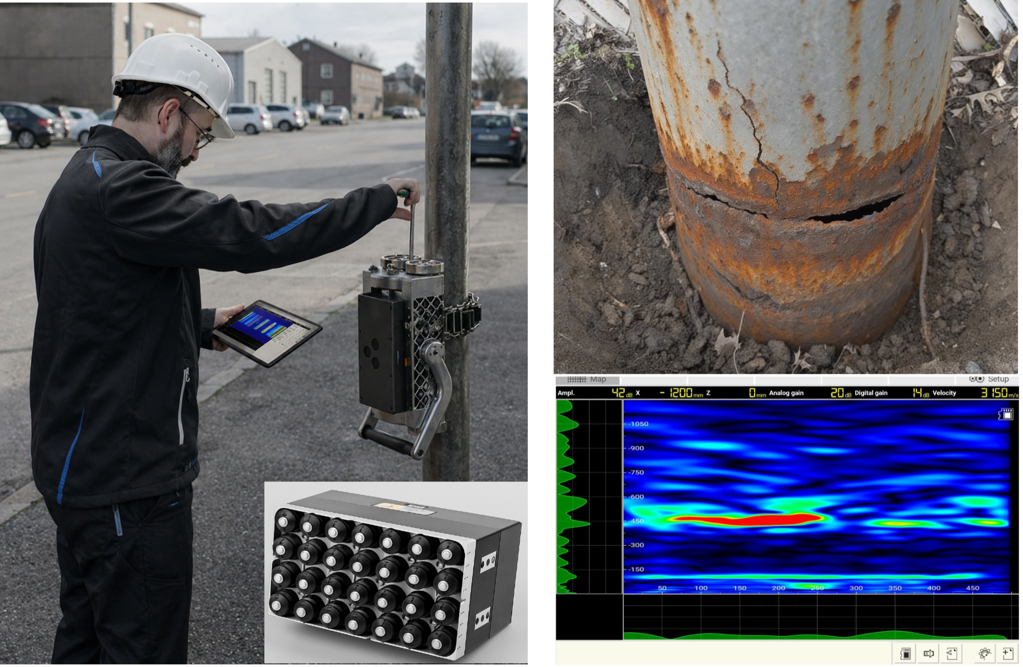
Because DPC transducers generate shear-wave components, they can excite guided waves in bounded media efficiently. This capability is used for:
- inspection of extended structural elements;
- diagnostics of structures with limited accessibility, such as lighting poles;
- detection of defects located far from the excitation point — for example, corrosion beneath supports.
A practical advantage of guided-wave inspection: when ultrasonic waves travel in bounded media where the propagation path is set by the object’s geometry, hidden or inaccessible regions can be inspected — including areas at considerable distances from the ultrasonic excitation point.
Another advantage of guided-wave excitation with DPC transducer systems, besides the absence of liquid couplants, is the ability to generate horizontally polarized shear (SH) waves in both electrically conductive and non-conductive materials — including inspection through paint and protective coatings.
A practical example is the detection of hidden corrosion in metallic utility poles with a guided-wave system built on an array of 32 DPC transducers. During inspection, the pole is scanned circumferentially with a step size of 20 mm, while a B-scan image is reconstructed in real time using the Synthetic Aperture Focusing Technique (SAFT).
5. Conclusion
This article has examined the physical foundations, construction details, and fields of application of low-frequency dry-point-contact piezoelectric transducers for ultrasonic non-destructive testing. We have shown that DPC technology provides efficient transfer of ultrasonic energy into the test object without liquid couplants — a decisive factor for inspecting coarse-grained, porous, and structurally heterogeneous materials such as concrete, stone, and composites.
The step from single-element probes to multi-element DPC arrays, combined with advanced imaging algorithms like SAFT and TFM, markedly raises image quality, spatial resolution, and the reliability of defect detection in strongly scattering media. Field experience confirms the effectiveness of the technology for thickness gauging, reinforcement mapping, detection of voids and cracks, and ultrasonic characterization of materials.
DPC transducers thus represent a promising path in the development of advanced ultrasonic testing systems — especially for civil engineering and industrial structures inspected under harsh environmental and coupling conditions.
References
- Kozlov, V.N., Samokrutov, A.A., Shevaldykin, V.G. Thickness Measurements and Flaw Detection in Concrete Using the Ultrasonic Echo Method. Nondestructive Testing and Evaluation, 13(2), 73–84, 1997.
- Shevaldykin, V.G., Kozlov, V.N., Samokrutov, A.A. Inspection of Concrete by Ultrasonic Pulse-Echo Tomograph with Dry Contact. Proceedings of the 7th European Conference on Non-Destructive Testing, Copenhagen, Denmark, 1998.
- Haza, A.O., Petersen, C.G., Samokrutov, A. Three-Dimensional Imaging of Concrete Structures Using Ultrasonic Shear Waves. German Instruments SA, Denmark, 2011.
- Samokrutov, A., Plinchuk, R., Bulavinov, A., Shevaldykin, V. Method for the Non-Destructive Examination of a Test Specimen by Use of Ultrasound. U.S. Patent 11,092,572 B2, 2021.
- Bulavinov, A., Pinchuk, R., Samokrutov, A., Shevaldykin, V. Advanced Tomographic Imaging Techniques for Quality Assessment of Concrete Structures by Means of Ultrasound. Proceedings of NDE NucCon 2023, Espoo, Finland.
Frequently Asked Questions
What is a dry-point-contact (DPC) transducer?
A DPC transducer couples ultrasound into a material through small, hard contact tips rather than a flat face and a liquid couplant. The tips form localized mechanical contact, so the probe transmits sound dry — without gel, water, or oil. DPC transducers work in the low-frequency band of approximately 20 to 400 kHz.
Do DPC transducers need couplant?
No. The point-contact design transmits ultrasound with no liquid couplant at all. That is the main reason DPC transducers are suited to field inspection of porous and rough materials, where a couplant would be impractical or would distort the readings.
Which materials suit DPC ultrasonic testing?
Coarse-grained, porous, and strongly scattering materials such as concrete, stone, and fibre-reinforced composites — plus surfaces that are rough, curved, coated, or at elevated or reduced temperature. These are the cases where conventional high-frequency contact probes lose their signal.
How is DPC different from EMAT and air-coupled ultrasound?
All three avoid liquid couplant, but they work differently. EMAT generates ultrasound electromagnetically and only works on conductive materials. Air-coupled systems transmit across an air gap and lose a great deal of energy, so they are unsuitable for pulse-echo testing. DPC uses direct mechanical point contact, which yields higher transmission efficiency at low frequency and works on non-conductive materials such as concrete in both pulse-echo and through-transmission modes.
Can DPC transducers measure concrete strength?
Indirectly. With the Ultrasonic Pulse Velocity Test (UPVT), DPC arrays measure how fast sound travels through the concrete. Once calibrated against reference samples or destructive test data, that velocity correlates with compressive strength.
What can DPC arrays detect in concrete?
Thickness from one-sided access, reinforcement and embedded metal, voids and honeycombing, crack depth, and strength by UPVT. Combined with SAFT and TFM imaging, the arrays reconstruct tomographic images of the interior.
Need Help Choosing the Right Technology?
If you’re evaluating which technology fits your inspection program, our engineering team is happy to talk it through.