
Ultrasonic Thickness Gauging: Piezoelectric vs EMAT
When an inspection plan calls for wall-thickness data, the instrument market essentially offers two ultrasonic paths: conventional piezoelectric (piezo) thickness gauges and electromagnetic acoustic transducer (EMAT) instruments. The first is the long-proven, couplant-based standard. The second builds the sound wave directly inside the metal, which removes the couplant from the process and opens up measurements on hot, coated, and heavily corroded surfaces.
This guide puts the two technologies head to head: the physics each one relies on, where each one performs best, where each one hits its limits, and a step-by-step framework for choosing the right tool for the conditions you will actually meet on site.
Why Thickness Data Still Drives Integrity Programs
Infrastructure keeps aging, safety requirements keep tightening, and maintenance windows keep shrinking. All of that has pushed expectations for thickness inspection higher than they used to be. Ordinary readings on clean steel at room temperature are well within the reach of mature, well-understood instruments.
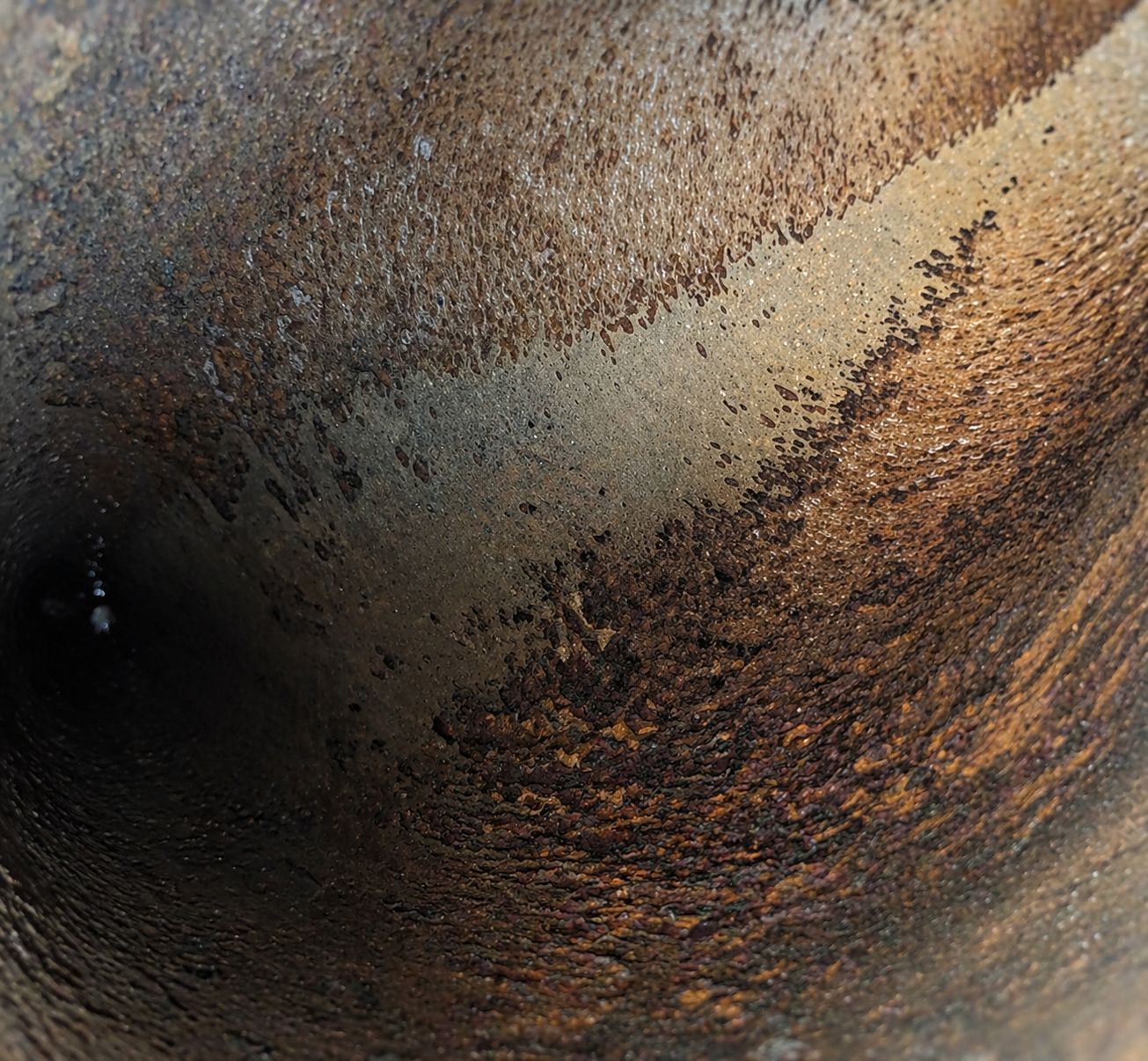
The measurements that decide the outcome of a program today are the difficult ones: hot process piping that cannot be taken out of service, painted surfaces where removing the coating would take longer than the inspection itself, and corroded steel in elevated or confined locations where every additional step adds safety risk. Inspections like these are what separate a serious asset-integrity program from a routine box-checking exercise.
How Every Ultrasonic Thickness Gauge Measures
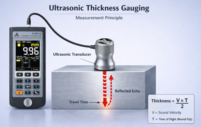
The principle is familiar from medical ultrasound and even parking sensors, adapted to industrial metals. Ultrasonic thickness gauging determines the wall thickness of a part from one side only — no cutting, no drilling, and no shutdown required.
The working principle behind every such instrument is pulse-echo [1]. The gauge fires a brief pulse of high-frequency sound into the material. The wave propagates through the metal at a known velocity, reflects off the back wall, and returns. The instrument measures the total round-trip time and converts it to thickness with a straightforward formula:
T = (V × t) / 2
where:
- T = thickness of the material
- V = sound velocity in that particular material
- t = time the pulse needed to travel there and back
The result is halved because the wave crosses the wall twice — once going out and once coming back.
Sound velocity is a material property, not an instrument setting. It is approximately 5,920 m/s in carbon steel and about 6,320 m/s in aluminum. Since the gauge must be told which velocity applies to the part under test, calibration against a reference block of known thickness before each job is standard practice.
The physics of the measurement is simple. The engineering problem is delivering the sound into the metal. Air is almost a perfect acoustic barrier: because of the extreme impedance mismatch between a transducer face and an air gap, more than 99.9% of the acoustic energy reflects away before it can enter the test piece [2]. Solving that coupling problem is what divides the two technologies.
Piezoelectric instruments solve it with a liquid couplant — a gel or fluid that displaces the air between the probe face and the metal surface. EMAT takes the opposite route: it creates the acoustic wave directly inside the metal with electromagnetic fields, so the air-gap problem never arises.
Both technologies can also work with different wave modes. Longitudinal (compression) waves are the default in conventional piezo gauging. Shear waves, in which material particles oscillate perpendicular to the propagation direction, travel at roughly half the longitudinal speed and give finer measurement resolution. EMAT probes naturally excite shear horizontal (SH) waves, which carries its own practical advantages, described in the sections below.
Piezoelectric UT: The Industry Workhorse
How piezo transducers operate
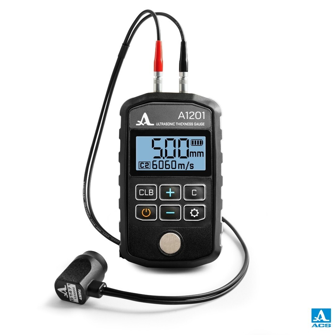


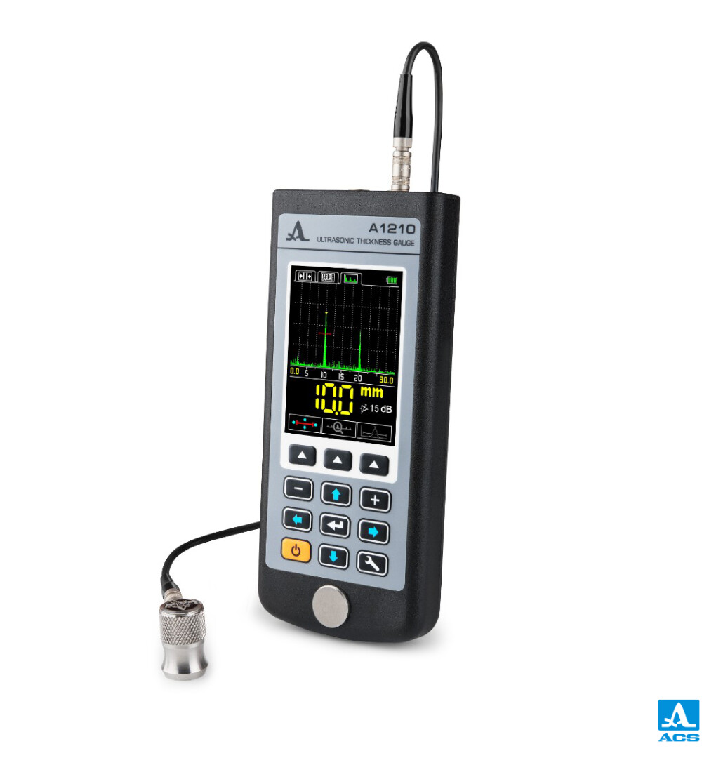
Piezoelectric probes form the foundation of the whole field. A polarized ceramic element (PZT) turns electrical pulses into mechanical vibration and converts returning echoes back into electrical signals. Matching layers maximize the transfer of acoustic energy into the test material, while a backing block suppresses ringing so the pulse stays short and the resolution stays high.
One condition is non-negotiable: couplant. A thin layer of gel, glycerin, or oil must occupy the air gap between the probe face and the metal. Without it, no sound enters the material at all.
For thickness measurement, three probe configurations dominate:
- Single-element probes — general-purpose measurements on smooth surfaces
- Dual-element probes — separate transmit and receive crystals angled to form a focal zone; the default choice for corrosion surveys on rough or pitted steel
- Delay-line probes — a plastic standoff that suits thin-wall measurement and elevated-temperature work
Equipment manufacturers cover all three configurations across different workflows — from pocket-sized units like the A1207 PenGauge to the A1210 with full A-scan display.
Where piezo genuinely performs best
Piezo became the default for solid reasons:
- Top absolute accuracy. On clean surfaces at ambient temperature, resolution down to 0.01 mm is routine.
- Lowest cost per reading. The instruments are affordable, transducers are interchangeable, and consumables cost no more than a bottle of gel.
- Broadest material coverage. Metals, plastics, composites, glass, ceramics — for non-metallic materials, piezo is frequently the only practical answer.
- Huge installed base. Every NDT technician in the world learned on piezo equipment. There is no learning curve and no shortage of qualified operators.
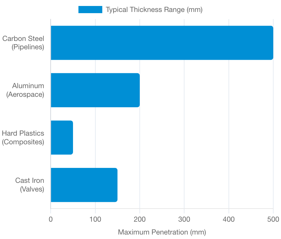
Measurement ranges differ by material and frequency choice: higher frequencies resolve thinner walls, while lower frequencies penetrate deeper into attenuative materials such as cast iron. These ranges assume standard contact transducers with the frequency matched to the task.
Where piezo starts to struggle
Every limitation of piezo traces back to the same root: the couplant and the surface it must sit on.
- Couplant dependency. Gel runs off vertical surfaces, freezes in sub-zero weather, boils on hot steel, and contaminates food-grade or pharmaceutical environments. Spread over thousands of measurement points, the seconds spent applying and wiping it away accumulate into hours.
- Surface preparation. Piezo probes demand reasonably smooth, clean metal. Loose paint, heavy rust, mill scale, and weld spatter must be removed before the first reading. On a large pipeline or a tank floor, the grinding and brushing can consume more time than the inspection itself.
- Temperature ceiling. Standard probes deteriorate above roughly 50°C. Specialized high-temperature delay lines extend the range to about 500°C, but only with brief-contact technique, constant re-zeroing, and couplants that burn off fast. Each reading turns into a race against thermal damage.
Behind all of this stands one physical fact: over 99.9% of acoustic energy reflects at a steel–air interface [2]. Couplant exists to defeat that barrier. Eliminating it calls for a fundamentally different way of producing the sound wave — which is precisely what EMAT offers.
EMAT: Generating Sound Inside the Metal
How EMAT works
Each EMAT probe relies on two active elements: a magnet that establishes a magnetic field inside the metal, and an RF coil positioned just above the surface.
When the coil is driven with alternating current in the ultrasonic frequency range, it induces eddy currents in the skin layer of the metal below. Those eddy currents interact with the magnetic field, and the resulting Lorentz force physically shakes the crystal lattice of the material [3]. That mechanical disturbance is the ultrasonic wave. On the way back, the back-wall echo reverses the process and induces a small voltage in the same coil. The Lorentz-force mechanism operates on any electrically conductive metal, including aluminum, copper, and stainless steel.
In ferromagnetic metals such as carbon steel and cast iron, a second mechanism acts in parallel. Magnetostriction — the tendency of magnetic domains to change shape in an applied field — adds substantial signal strength on top of the Lorentz force [4]. That is why EMAT echoes are typically stronger on carbon steel than on aluminum. The combined effect is a clean echo without a single drop of couplant.
The essential insight: the test material itself becomes the transducer. The sound wave is born inside the metal rather than being pushed in from outside through a gel layer. There is no air-gap problem left to solve.
Why removing couplant changes everything
Dropping the couplant is far more than a convenience upgrade — it eliminates the single largest bottleneck in field thickness inspection:
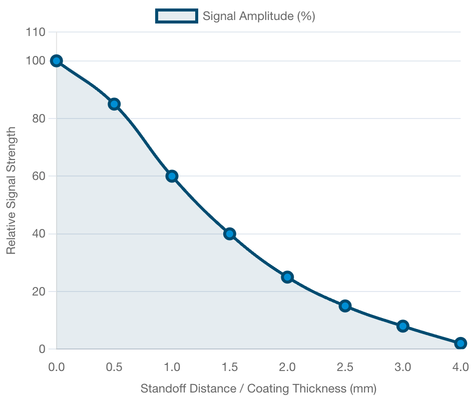
- Coated surfaces. EMAT measures through paint, primer, epoxy, and light corrosion up to roughly 3–4 mm thick, and the display reports metal thickness only. No stripping, no grinding.
- Corroded and scaled metal. Rust, mill scale, and oxide layers that would stop a piezo probe are largely transparent to EMAT.
- Corrosion under insulation (CUI). Surveys can proceed without removing cladding or weather jacketing, reducing scaffolding time and personnel exposure.
- Hot surfaces. There is no couplant to boil off. EMAT probes take readings on steel at temperatures up to 800°C, and some configurations reach 1,000°C.
- Contamination-sensitive environments. No gel residue remains on the surface — relevant for food processing, pharmaceutical production, and cleanrooms.
- Speed. Place the probe on the surface and read. No preparation, no cleanup. Typical inspection speed is roughly double that of piezo on comparable assets.
Signal strength falls as the gap between the probe and bare metal grows. Through about 3 mm of coating, the echo still carries enough strength for dependable thickness readings. Past that point, accuracy begins to decline — the practical boundary of through-coating measurement with current EMAT instruments.
Permanent magnets vs pulsed electromagnets


Early EMAT probes used permanent neodymium (NdFeB) magnets to supply the bias field. They worked, but brought their own problems on ferromagnetic steel:
- Severe magnetic drag. The probe clamps to the steel so forcefully that inspectors cannot slide it [5]. Continuous scanning becomes impossible, and every reading degrades into a lift-and-place exercise.
- Debris pickup. Metal shavings, scale, and dirt cling to the magnetized face constantly, degrading signal quality and demanding frequent cleaning.
- Thermal vulnerability. NdFeB magnets have a relatively low Curie point. They lose magnetization at elevated temperatures, making them unreliable on hot assets without bulky cooling hardware.
The answer is the pulsed electromagnet: a wound copper core instead of a permanent magnet. The instrument fires a short, powerful DC pulse through the electromagnet at exactly the instant the RF coil transmits its acoustic pulse. The magnetic field exists only for a fraction of a millisecond — the duration of the measurement itself.
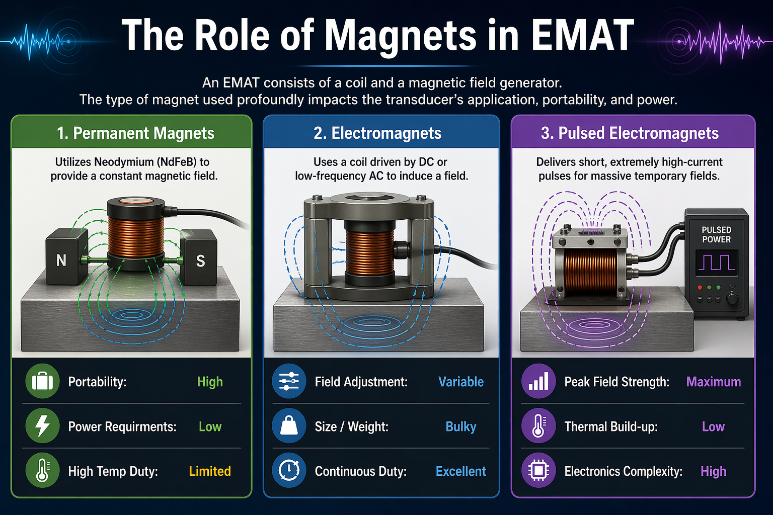
How the magnet choice shapes the transducer’s application range, portability, and power demand is worth spelling out, because the three main approaches differ markedly:
- Permanent magnets. Neodymium (NdFeB) supplies a constant field. Portability is high, power requirements are low, but high-temperature duty is limited.
- Conventional electromagnets. A DC- or low-frequency-AC-driven coil induces the field. Field strength is adjustable and continuous duty is excellent, but the assembly is bulky.
- Pulsed electromagnets. Short, extremely high-current pulses create massive temporary fields. Peak field strength is the highest of the three, thermal build-up is low, and electronics complexity is high.
In practice, the pulsed approach delivers:
- No magnetic drag. The probe stays unmagnetized 99.9% of the time, so inspectors can glide it across the surface for continuous B-scan profiling.
- No debris attraction. The sensor face stays clean, keeping liftoff distance — and readings — consistent.
- No thermal degradation of magnets. There is no permanent magnet to demagnetize at high temperature.
- Tunable output. Engineers can adjust the pulse voltage to optimize signal strength for different materials and wall thicknesses — something a fixed permanent magnet cannot do.
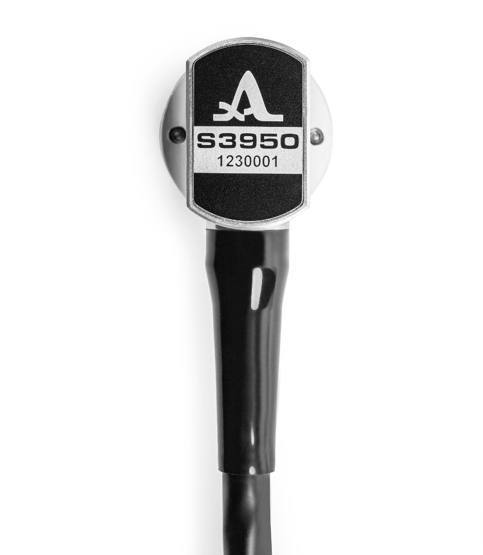
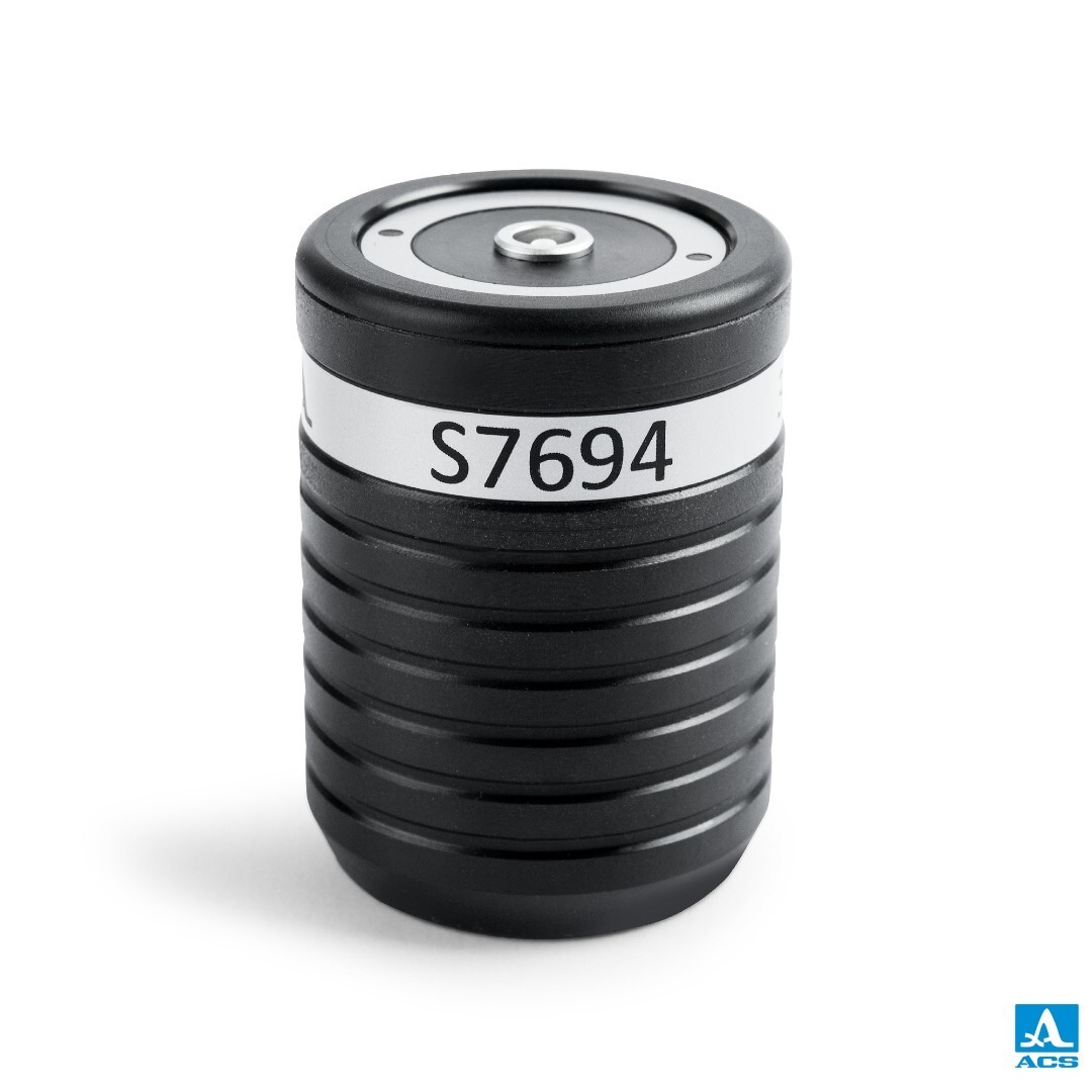
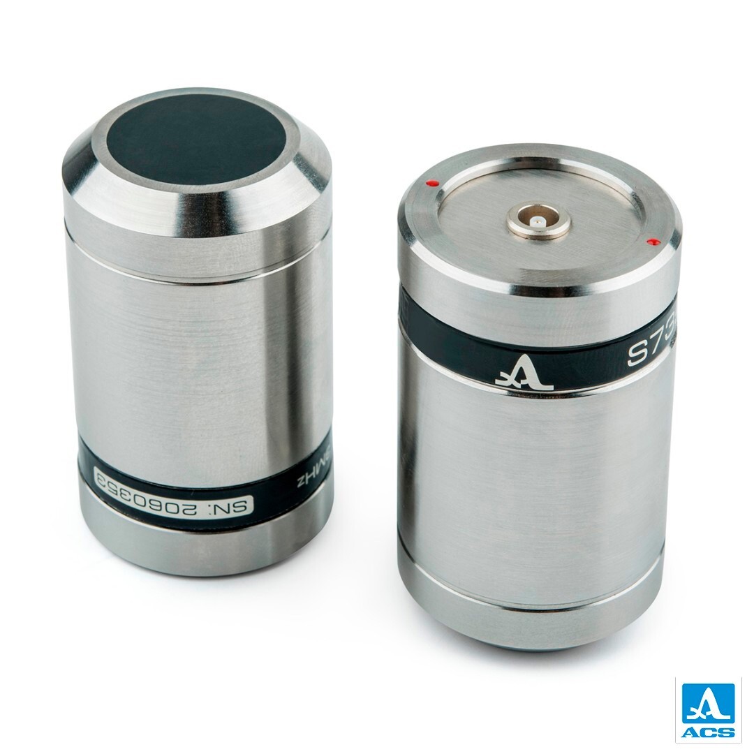
Equipment manufacturers build EMAT transducers in both configurations: pulsed-magnetization probes with an integrated cable, and permanent-magnet probes (for example the S7692, S7694, S7392, and S7394 families) for work where magnetic drag is not a factor, such as fixed-point measurements or lighter alloys.
High-temperature capability


Standard ultrasonic couplant boils at around 150°C. Specialized high-temperature gels push the usable limit to roughly 300°C with brief-contact technique. Past that point, piezo gauging becomes impractical.
EMAT operates on an entirely different scale. The A1270 EMAT thickness gauge with its high-temperature transducer (S73 series) produces stable readings on surfaces up to 800°C, and some research configurations have reached 1,000°C.
This is not a marginal improvement over piezo — it is a different operating category. It enables wall-thickness measurement on live refinery distillation columns, boiler water-walls under full steam load, hot-rolled steel on the mill line, and chemical process piping that cannot be taken offline. Jobs that once demanded a shutdown or a cooling window can now be inspected during normal operation.
Limitations, stated plainly
EMAT is not a universal replacement for piezo. Its boundaries matter in real work:
- Material compatibility. EMAT requires electrically conductive — and works best on ferromagnetic — materials. Plastics, composites, glass, and ceramics fall outside its range; for those, piezo remains the only option.
- Signal-to-noise ratio. EMAT echoes are inherently weaker than piezo echoes. In certain conditions, particularly heavy pitting corrosion, that can affect readability. Modern amplifiers and smart gating compensate in most cases, but the difference is real.
- Minimum thickness. The RF excitation pulse creates a first-echo dead zone of roughly 6 mm in steel, so the gauge cannot measure that range from the initial pulse alone. Modern instruments get around it with echo-to-echo timing and advanced signal processing — for example, the A1270 measures down to 0.9 mm on steel [6]. The dead zone is a physics characteristic of the method, not a hard instrument limit.
- Frequency range. EMAT works at lower frequencies than high-frequency piezo transducers, which restricts its precision on very thin or finely layered materials where high-frequency resolution is required.
- Single-element configuration only. A dual-element EMAT probe cannot be built, which limits detection performance on certain corrosion morphologies such as pitting.
- Instrument cost. EMAT gauges cost more than basic piezo instruments. The economics pencil out once surface-prep time, consumables, downtime savings, and access costs enter the calculation — but the upfront price is higher.
Every technology has a working envelope, and honest engineers respect that. EMAT’s envelope covers exactly the conditions where piezo struggles most.
EMAT Thickness Gauging in Automated Inspection
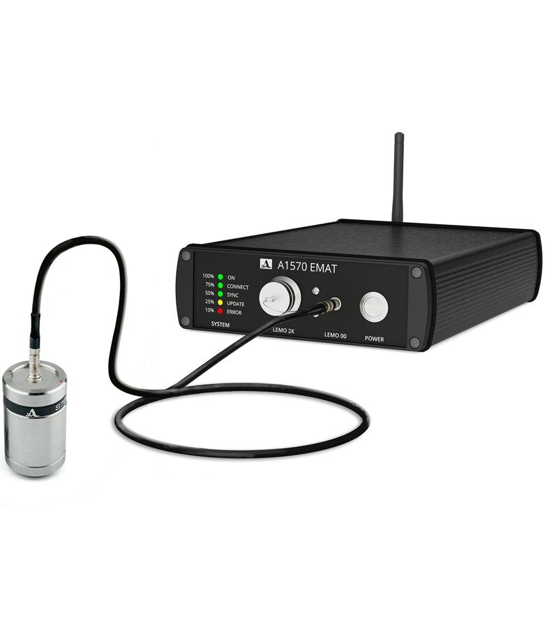
Handheld EMAT gauges solve the access and surface-prep problems for field inspectors. But the same couplant-free physics also makes EMAT a natural fit for automated and robotic inspection systems.
Automating conventional piezo is possible, yet it demands a constant couplant supply: fluid reservoirs, pumps, nozzles, and recovery systems that add weight, complexity, and failure points to the rig. If the couplant feed dries up mid-scan, data acquisition stops. If it floods unevenly, readings drift.
EMAT removes that whole subsystem. No fluid to supply, no mess to recover — the probe only needs proximity to the metal surface and an electrical connection. That simplicity converts directly into more reliable continuous scanning.
Pulsed-electromagnet probes are particularly automation-friendly. Because the magnetic field is active only during the measurement pulse, the probe does not stick to ferromagnetic surfaces. A robotic crawler or motorized carriage glides the sensor smoothly without fighting magnetic drag, producing clean B-scan wall profiles over long runs.
Where this matters most:
- Boiler water-wall inspection. Automated EMAT rigs scan hundreds of tubes per shift, without scaffolding crews applying and cleaning couplant at every point.
- Storage tank floors. Crawlers map remaining wall thickness under epoxy or bitumen coatings without stripping them first.
- Inline pipe mills. EMAT integrates into production lines for real-time wall-thickness verification during manufacturing, at speeds contact probes cannot match.
- Offshore and confined-space assets. Robotic platforms carry EMAT sensors into locations where sending a human inspector is expensive, slow, or hazardous [7][8].
For integrators, OEM EMAT pulser-receiver units are available purpose-built for this role — designed for integration into third-party scanning systems and automated inspection rigs, supporting both pulsed-magnetization and permanent-magnet transducers, with bipolar burst excitation across a 1–10 MHz frequency range, Ethernet and WiFi data interfaces, and an SDK compatible with the SCPI industrial protocol for straightforward integration into mapping and reporting software.
Other Approaches Worth Knowing
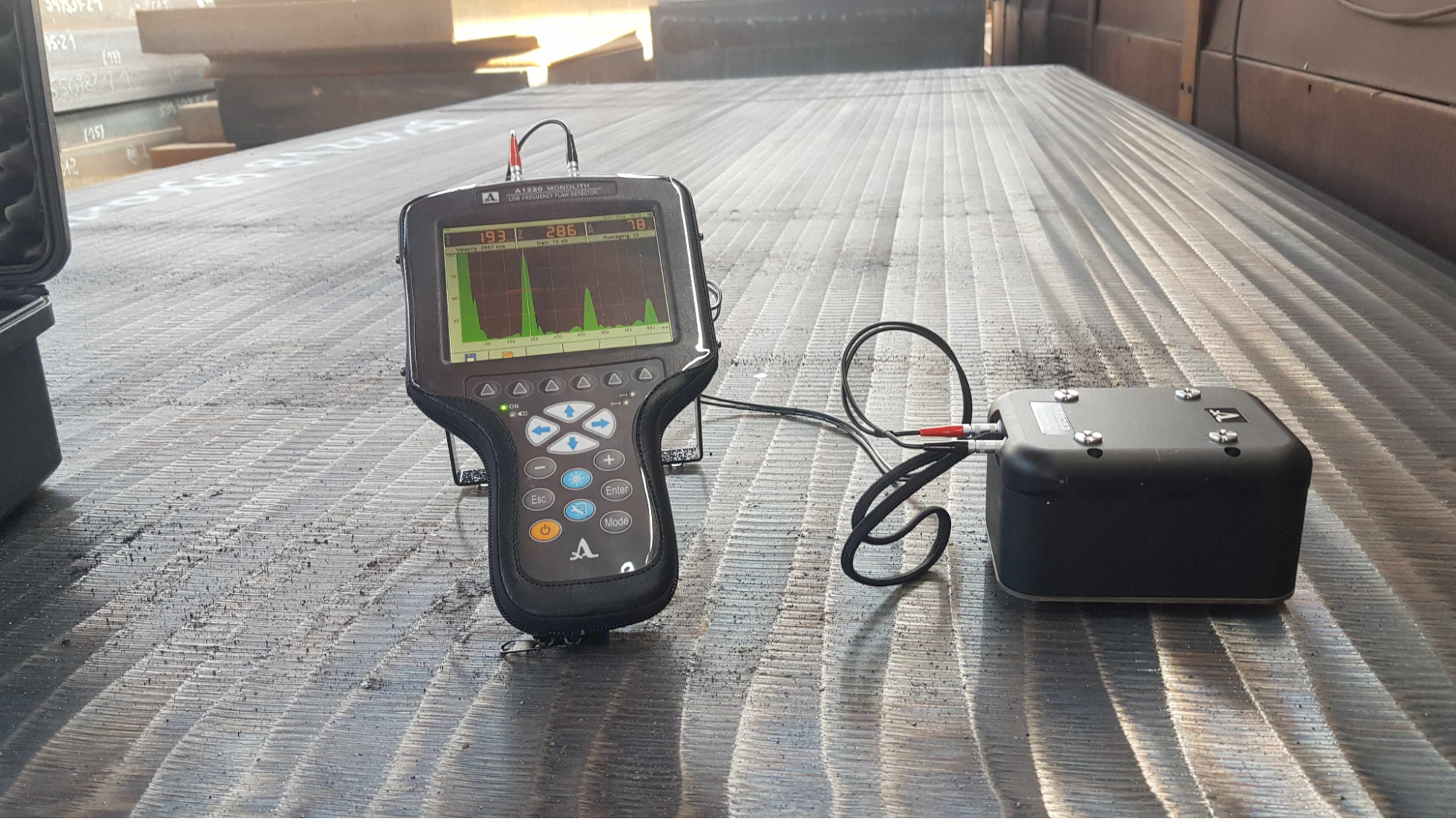
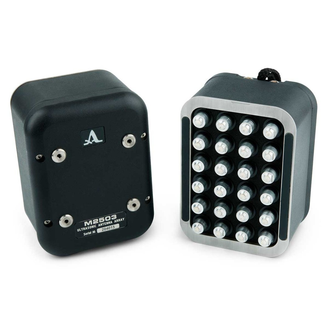
Piezo and EMAT cover the overwhelming majority of industrial thickness gauging, but both operate best within a certain frequency and penetration range. When the material is extremely thick, highly attenuative, or not metallic at all, a different transducer class takes over.
Dry-Point-Contact (DPC) transducers run at far lower frequencies — typically 20 kHz to 400 kHz. Instead of a flat wear face and couplant, they use a spring-loaded point or pin pressed directly against the surface, mechanically coupling low-frequency acoustic energy into the material without any liquid.
That low frequency is what gives DPC its reach. Where standard piezo and EMAT signals attenuate and scatter in thick or granular materials, DPC pushes through. Inspection ranges can run from several hundred centimeters to several meters — practical for applications invisible to higher-frequency methods.
Where DPC finds its niche:
- Heavy-gauge steel plate too thick for conventional UT frequencies
- Concrete structures, for ultrasonic monitoring of thickness or crack depth
- Wood and timber in structural assessment
- Highly attenuative composites and cast materials with coarse grain structures
The trade-offs are straightforward. Low frequency means low resolution, so DPC cannot match the fine detail of piezo or EMAT on standard metal walls. The equipment is more specialized, the application scope is narrower, and it does not replace either technology for routine metal inspection. It fills a gap neither piezo nor EMAT was designed to reach.
Choosing the Right Technology: A Practical Framework
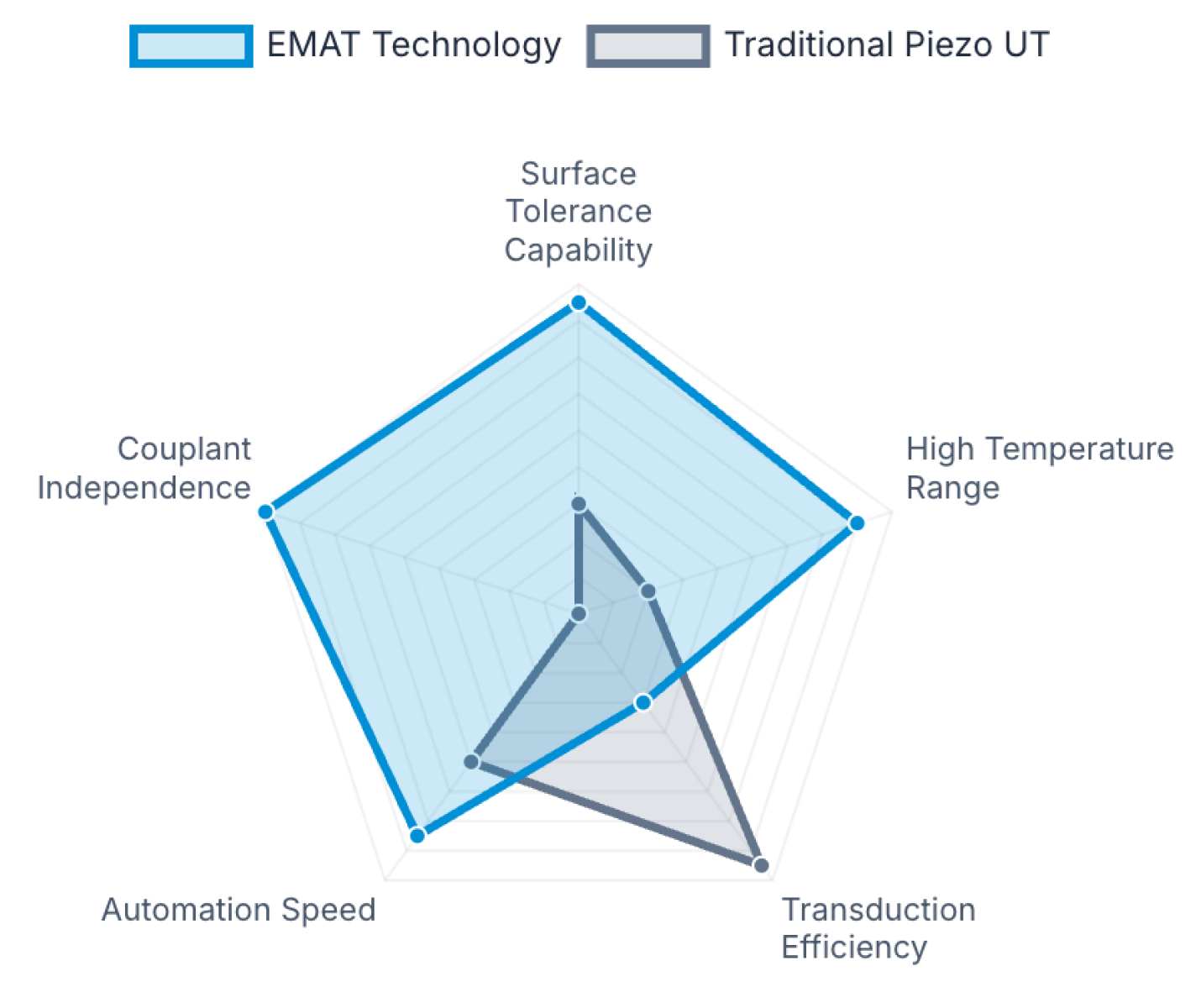
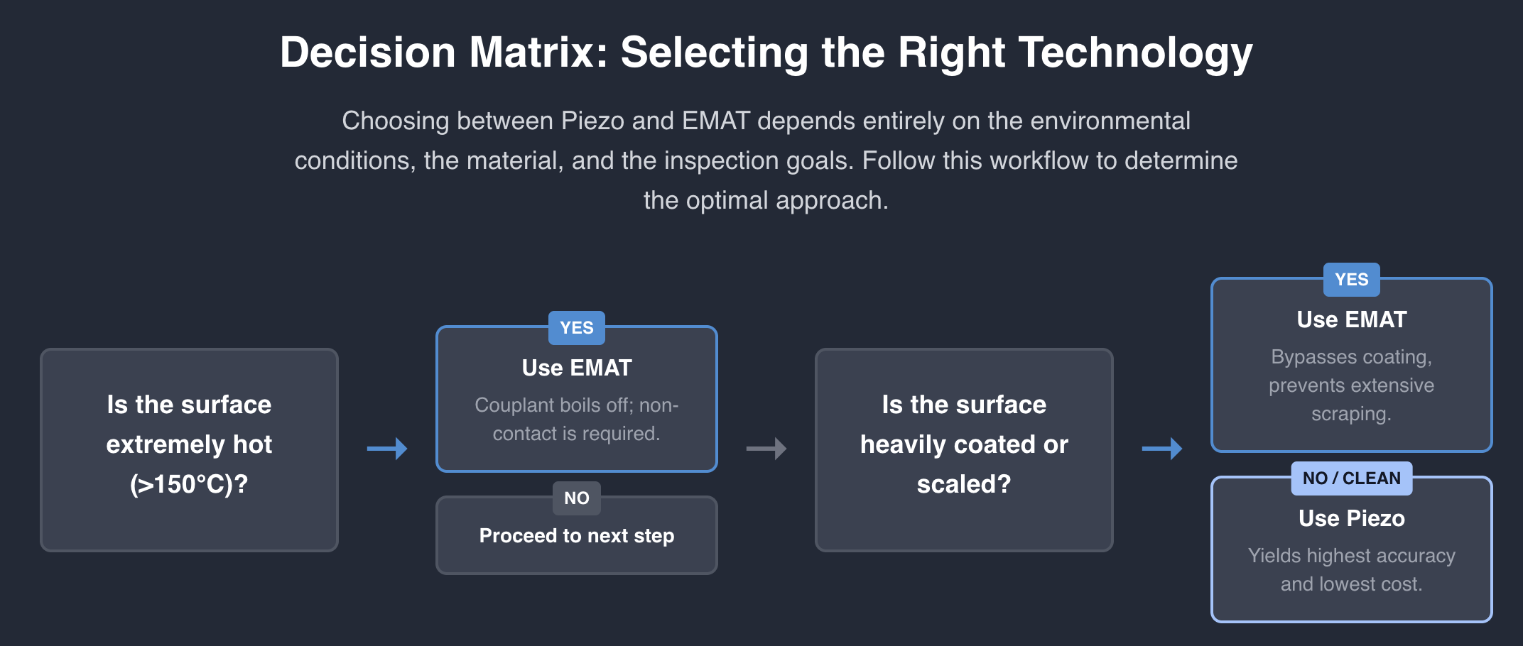
There is no single best ultrasonic thickness gauge — only the right one for the conditions in front of you. Broadly, EMAT pulls ahead on surface tolerance, couplant independence, high-temperature range, and automation speed, while piezo leads on transduction efficiency and material versatility. Neither wins everywhere.
One caution: a performance-comparison profile should be read as a map of relative strengths, not as a picture of overall market usage. EMAT is a powerful specialist for extreme-condition challenges; conventional piezo UT remains the industry’s predominant, most broadly applied tool — the reliable daily driver and the proven standard for everyday ultrasonic inspection across countless sectors for decades. Where extreme conditions are absent, it is still the preferred choice for the overwhelming majority of common inspections.
The questions below follow the order that usually matters most on a real job.
What is the surface temperature?
Above 150°C, standard piezo couplant is out. Specialized high-temperature piezo probes reach about 500°C with brief contact, but add complexity. Above 500°C, EMAT is the practical choice — the A1270 with the S73-series transducer handles surfaces up to 800°C without couplant or cooling.
Is the surface coated, corroded, or scaled?
If yes, and you would rather not strip it, EMAT is the shorter path. It reads through paint, primer, and light corrosion up to about 4 mm. Piezo can measure through paint in through-paint mode, but still needs couplant and a reasonably smooth finish underneath.
Is couplant practical in this environment?
Some situations rule out gel entirely: production lines where liquid contamination is unacceptable, remote locations where consumable resupply is a logistics problem, confined spaces where cleanup is difficult, cleanroom or food-grade environments. In any of these, EMAT’s couplant-free operation is not just convenient — it is necessary.
Do you need continuous scanning or spot checks?
For spot checks on accessible surfaces, either technology works well. For continuous scanning — especially on ferromagnetic steel — pulsed-electromagnet EMAT holds a clear advantage: no magnetic drag, no couplant trail, smooth B-scan profiling along the surface.
What material are you inspecting?
This is piezo’s exclusive territory. EMAT requires an electrically conductive material and performs best on ferromagnetic metals. Measuring plastics, composites, glass, ceramics, or certain low-conductivity non-ferrous alloys? Piezo is the only option.
What do the budget and team capability look like?
For standard corrosion surveys on clean, accessible, ambient-temperature steel, piezo gauges deliver excellent results at the lowest cost: cheaper instruments, widely available transducers, and a technique every trained NDT operator already knows. When conditions get harder, the cost equation shifts. Time saved on surface preparation, eliminated consumables, reduced scaffolding, and avoided shutdowns add up fast. In those scenarios, the higher upfront cost of an EMAT gauge pays back within the first major campaign.
The answers to these questions tend to sort themselves out naturally: piezo for standard conditions, EMAT for the tough ones, both in the toolkit for full coverage.
Closing
The right instrument is the one that matches the conditions of the job. Clean surface, ambient temperature, any material from steel to plastic — a piezo gauge remains the most practical and cost-effective answer. But when the job pushes back — hot metal, coated surfaces, corroded piping, limited access, no time for prep — EMAT earns its place.
Delta Test Technologies carries both families of instruments. The piezo ultrasonic thickness gauges cover standard thickness measurement across a wide range of materials and applications, while the A1270 EMAT handles the inspections that used to demand shutdowns, grinding crews, and temperature windows. If you are evaluating which technology fits your inspection program, our team is happy to talk it through.
References
[1] “Ultrasonic Testing of Materials”, 4th fully rev. ed., J. Krautkrämer and H. Krautkrämer, Springer-Verlag, Berlin, Germany, 1990.
[2] “Acoustic Impedance”, Innovation.world. Available: https://innovation.world/invention/acoustic-impedance/
[3] “Application of Electromagnetic Ultrasonic Testing Technology in Pipeline Defects”, Coatings, vol. 16, no. 1, 2026. Available: https://www.mdpi.com/2079-6412/16/1/133
[4] “Influence of Magnetostriction Induced by the Periodic Permanent Magnet Electromagnetic Acoustic Transducer (PPM EMAT) on Steel”, ResearchGate, 2021. Available: https://www.researchgate.net/publication/356398045
[5] “A Lorentz Force EMAT Design with Racetrack Coil and Periodic Permanent Magnets for Selective Enhancement of Ultrasonic Lamb Wave Generation”, PMC, 2023. Available: https://pmc.ncbi.nlm.nih.gov/articles/PMC9824448/
[6] “Thickness Measurements with EMAT Based on Fuzzy Logic”, Sensors, PMC, 2024. Available: https://pmc.ncbi.nlm.nih.gov/articles/PMC11244354/
[7] “Development of an Ultrasonic Inspection Robot Using an Electromagnetic Acoustic Transducer for a Lamb Wave and an SH-plate Wave”, ResearchGate, 2004. Available: https://www.researchgate.net/publication/8654256
[8] “Towards Guided Wave Robotic NDT Inspection: EMAT Size Matters”, ResearchGate, 2019. Available: https://www.researchgate.net/publication/338200961