
How to Choose an Ultrasonic Transducer for NDT
Every ultrasonic measurement depends on one thing happening first: sound has to enter the test object. That is exactly what the transducer does. Which way is the right one depends on the acoustic properties of the material, the geometry of the part, the condition of the surface, the temperature of the object, and how much of it you can actually reach.
The correct transducer is the one that fits those real-world conditions: the coating that cannot be removed, the steel that is still hot from the process, the concrete that refuses to hold couplant, the weld that can only be approached from one side. Three core transducer families — piezoelectric, EMAT, and dry point contact — exist for one reason: no single sound-generation mechanism copes with all of these conditions at once. This guide explains how each family operates and is constructed, which inspection methods work with each, and how to choose a transducer for a real inspection task.
This article was prepared by the Delta Test Technologies team, drawing on hands-on field experience with the full transducer spectrum, from piezoelectric and EMAT probes to DPC arrays. Our instrument line covers the same range of technologies described here.
In this article
- The three core ultrasonic transducer families — piezoelectric, EMAT, and dry point contact — and the physics that separates them
- Transducer construction: active materials, matching layers, backing, coil geometries, magnet types, and optical sources
- Inspection methods and the transducer types each method runs on, including pulse-echo, PAUT / FMC/TFM, TOFD, ultrasonic tomography, and guided wave
- Where each technology genuinely beats the others, and where it does not
- A side-by-side comparison of operating frequencies, wave modes, surface tolerance, temperature, sensitivity, and cost
- A step-by-step decision framework for a real inspection task
- Adjacent technologies worth knowing: air-coupled and embedded sensors
Why the transducer defines the inspection
An ultrasonic inspection is specified by its method first. The starting questions are what is being inspected, which flaws matter, and which technique finds them: pulse-echo, phased array, tomography, or guided wave. The method is decided first. The transducer comes second, chosen to deliver that method on the surface and under the conditions you actually have. That second decision is what this article is about, because once the method is fixed, the transducer determines whether it works at all.
It is worth keeping two things separate that are often treated as one. Ultrasonic testing is the method. The transducer is the accessory that makes the method work on a real surface. Aim two probes built on different physical principles at the same flaw, drive them from the same instrument, and the results will not match. The instrument can only read what the transducer hands it.
The transducer is also the only element of the whole measurement chain that touches the test object. It operates on the surface as it really is, with its coating, temperature, curvature, and limited access. The instrument and its settings can be adjusted during the job. If the transducer does not suit the conditions, no setting will rescue the inspection.
That is why there is no universal best ultrasonic transducer. The three main sound-generation approaches described here — piezoelectric, EMAT, and DPC — exist because no single mechanism leads on surface condition, temperature, sensitivity, and access simultaneously. Each family is the strongest answer in a different corner of that trade-off.
The structure below starts with the inspection methods, then covers each transducer family in turn: how it generates sound and at which frequency, how the families compare head to head, and how to choose for the job you are facing.
Ultrasonic transducer basics
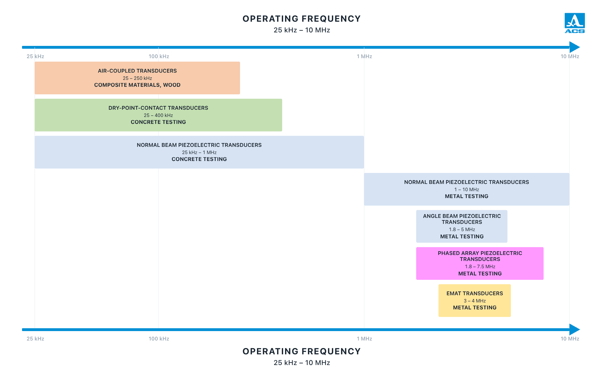
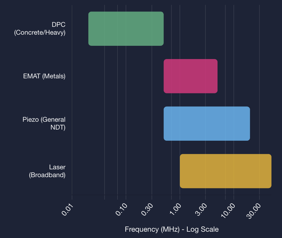
Industrial ultrasonic NDT operates in a band running from roughly 20 kHz to 25 MHz. Where a job sits in that band is set mostly by the material. Concrete and other coarse, heterogeneous materials force the work to the low end, in the tens of kilohertz, because only lower frequencies survive scattering. Thin metal sections and aerospace composites sit at the high end, from several megahertz up to 25 MHz, where short wavelengths resolve fine features. The principle behind the spread is simple: higher frequency gives finer resolution but less penetration, and the transducer is what sets the usable frequency.
Every transducer performs the same job twice. It converts an electrical pulse into a mechanical wave inside the part, then converts the returning wave back into an electrical signal. What separates the ultrasound generation methods is how they perform that conversion. Piezoelectric transducers use an active ceramic in direct contact with the part. EMAT uses electromagnetic fields — through the Lorentz force and magnetostriction — to generate the wave inside conductive metal. DPC transducers press a hard, spring-loaded tip against the surface and couple mechanically. A fourth method, laser excitation, generates the wave thermally with a short light pulse; it is included in the comparison tables for completeness. The three main families each have a dedicated section below.
Wave mode matters as much as the generation mechanism. Four modes carry most NDT work. Longitudinal waves move particles along the direction of travel and are the fastest, about 5,920 m/s in carbon steel [1]. They handle thickness gauging and most straight-beam flaw detection. Shear waves move particles across the direction of travel at roughly half that speed, about 3,255 m/s in steel [1], and underpin angle-beam weld inspection. Surface, or Rayleigh, waves stay within about one wavelength of the surface and find surface-breaking cracks. Guided waves — the Lamb and shear-horizontal modes in plates, the torsional and longitudinal modes in pipes — travel along the structure itself and can screen long pipe runs from a single position. Some transducers produce a mode naturally. Others need a wedge or a shaped coil to reach it.
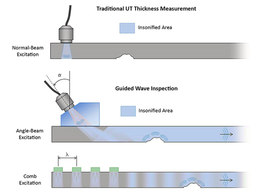
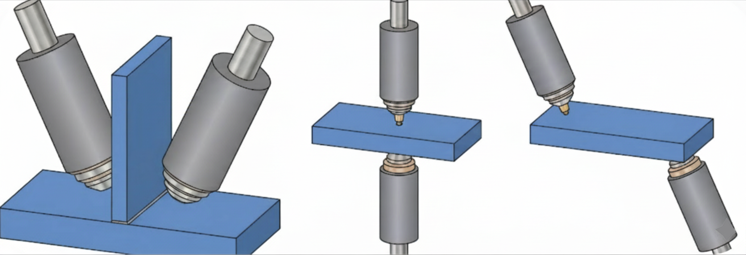
How a transducer launches the wave decides where the energy goes. Normal-beam excitation drives a localized beam for thickness measurement, while angle-beam and comb excitation set up guided waves that travel along the structure.
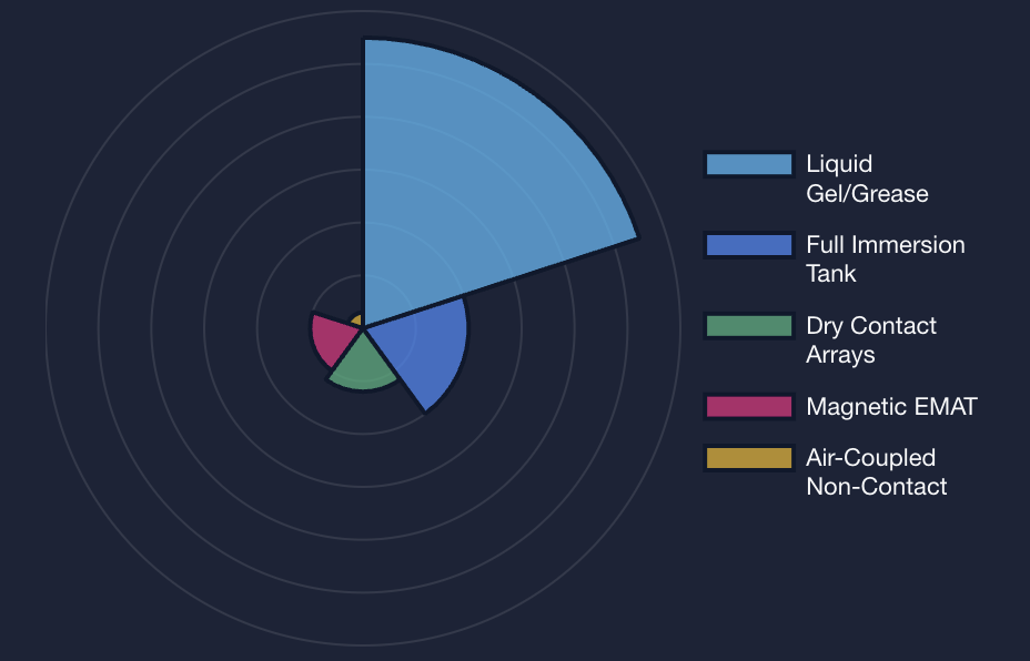
Everything rests on getting the wave across the boundary into the part, and that is the largest physical obstacle. Acoustic impedance is a material’s density times its sound velocity, and the gap between a solid and air is enormous. Steel sits around 45 × 10^6 Pa·s/m. Air sits near 415. At that mismatch, more than 99.9% of the energy reflects at a solid-air interface before any of it enters the part [2]. That is the coupling problem, and it runs through every section that follows. Each family is defined by how it solves or sidesteps that interface — with liquid couplant, a dry contact tip, an electromagnetic field, or a laser. In field practice today, most inspections still solve it the oldest way, with liquid couplant.
Inspection methods and their matching transducers
An inspection is specified by its method before any probe is selected. Engineers ask for a method by name, and each method runs on a particular set of transducers. This section lays out the methods; the transducer families that deliver them follow in later sections.
Pulse-echo is the default. One transducer sends the pulse and reads the echo, and it works on piezoelectric, EMAT, and DPC alike. It carries most thickness gauging — such as readings taken with a universal ultrasonic thickness gauge — weld joint inspection, and corrosion mapping.
Pitch-catch and through-transmission divide the job between two transducers, on the same face or on opposite faces. They earn their place on highly attenuating parts such as honeycomb composites, where a single-sided echo does not leave enough signal.
Angle-beam testing tilts the wave to catch defects a straight beam would miss, the classic arrangement for welds. A piezo probe does it with a wedge that mode-converts the longitudinal wave to shear. EMAT reaches the same result through coil geometry, with no wedge.
Phased array (PAUT) drives a multi-element array with timed delays to steer, focus, and sweep the beam electronically, with no moving parts. It is the dominant modern method for weld inspection and corrosion mapping. EMAT arrays can operate this way too, though the technique is less mature there.
Time-of-Flight Diffraction (TOFD) places two longitudinal-wave probes on either side of a weld and times the signals diffracted off crack tips. It sizes through-wall flaw height accurately and independently of orientation, with a near-surface dead zone that pulse-echo or PAUT has to cover.
Full Matrix Capture with the Total Focusing Method (FMC/TFM) fires each array element in turn while all elements receive, then focuses computationally at every pixel instead of at one fixed depth. That gives more uniform resolution than physical-focus PAUT. It is standard with DPC arrays for concrete tomography and increasingly standard with PAUT for welds and additive manufacturing.
Ultrasonic tomography builds a three-dimensional image from a dense array and FMC/TFM reconstruction — the standard approach for concrete from one side, with immersion piezo versions used on production parts.
Guided wave testing clamps a ring of transducers around a pipe and launches torsional or longitudinal modes that travel along the wall. From a single position it screens tens of metres of pipe, around 30 m each way in typically corroded refinery line and further in cleaner pipe [3].
The matrix below shows which method runs on which transducer family at a glance.
| Method | Piezoelectric | EMAT | Laser | DPC |
|---|---|---|---|---|
| Pulse-echo | Standard | Yes | Yes | Yes (concrete) |
| Pitch-catch / Through-transmission | Standard | Yes | Yes | Yes |
| Phased array (PAUT) | Standard | Research | Synthetic via scanning | Yes |
| TOFD | Standard | No | Possible | Not used |
| FMC / TFM | Standard | No | Possible | Standard (concrete) |
| Ultrasonic tomography | Immersion | Possible | Possible | Standard (concrete) |
| Long-range guided wave | Yes | Yes | Research | Yes |
| Immersion | Standard | Not used | Not applicable | Not used |
Knowing which method runs on which transducer is half the picture. The other half is the transducers themselves: how each family generates sound, where it excels, and where it does not. The following sections take each family in turn, beginning with the piezoelectric probe.
Piezoelectric transducers: the industry workhorse
The piezoelectric probe solves the coupling problem with a thin film of liquid. It is the industry default, and most ultrasonic inspection still starts with it.
How piezoelectric transducers work
A piezoelectric element converts electricity into sound and back. A short voltage pulse makes the element strain and launch a wave. When the echo returns, the same element turns that strain back into a voltage the instrument can read. That two-way conversion is the direct and inverse piezoelectric effect, and it is the whole basis of the probe.
The active material sets the starting performance. Most general-purpose probes use PZT ceramic, which is robust, low cost, and has a high piezoelectric coefficient. Dicing that ceramic and refilling the gaps with epoxy creates a 1-3 piezocomposite, which lowers the acoustic impedance toward that of the part, widens the bandwidth, and reduces cross-talk between array elements. Composite probes deliver 3 to 20 dB more sensitivity than standard ceramic probes, along with a shorter pulse, depending on the application [4]. Single-crystal PMN-PT pushes sensitivity and bandwidth further still, with measured gains of 5.2 dB in relative sensitivity and more than 27.7% in -6 dB bandwidth over a comparable PZT ceramic array [5]. It is also fragile, depolarizes under the high drive voltages heavy industrial work demands, and has a lower temperature ceiling, so it stays mostly in high-frequency, moderate-power arrays rather than general field use. For hot work, high-temperature materials such as bismuth titanate and lithium niobate, along with proprietary high-temperature ceramics, extend operation toward 550 °C.
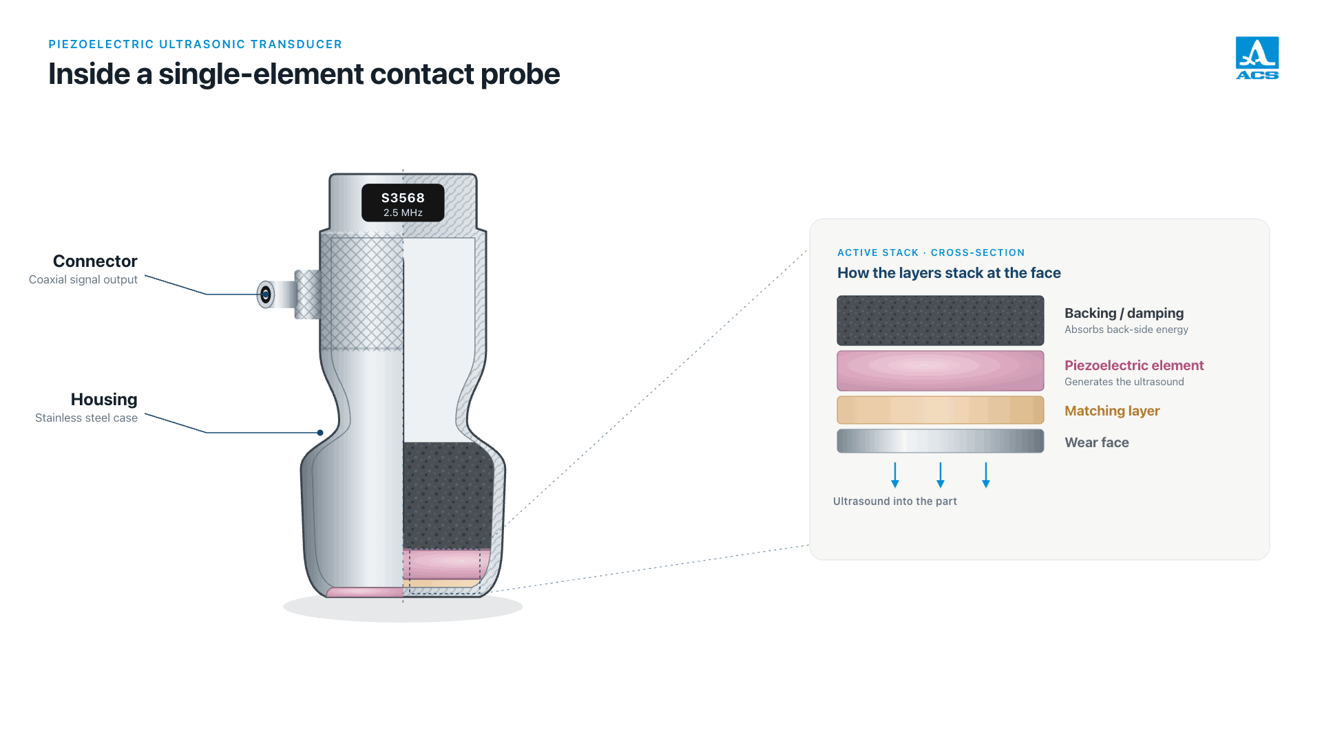
Around the active element sits a stack that shapes the pulse. The same impedance gap described above applies here, so a quarter-wavelength matching layer at the front steps the wave into the part, and its impedance is engineered — often as a bespoke composite — rather than selected off the shelf. A heavy tungsten-loaded backing block at the rear damps the ring. Heavier damping shortens the pulse and sharpens axial resolution; lighter damping holds the ring and lifts sensitivity at the centre frequency, so the designer picks a point on that curve to suit the inspection. A wear face protects the front, and the housing and cable complete the build.
Configurations
The same element appears in several forms. A single-element straight-beam probe is the default for thickness work. A dual-element probe splits transmit and receive onto separate crystals behind a delay line, which suppresses near-surface ringdown and makes it the standard for corrosion surveys on rough or pitted metal. An angle-beam probe sits on a plastic wedge that mode-converts the longitudinal wave into a refracted shear wave in steel — the classical setup for weld inspection. A phased array packs 16, 32, 64, or 128 elements into one housing and steers and focuses the beam electronically, with no moving parts, and it is the foundation for Total Focusing Method imaging.
Where piezoelectric genuinely excels
On clean, ambient-temperature metal, piezoelectric gives the best absolute sensitivity of any family at the lowest cost per reading. It covers the widest range of materials — metals, plastics, composites, and glass — which no other family matches. The installed base is enormous, so trained operators, calibration blocks, and written procedures already exist almost everywhere, and that ecosystem is itself a real advantage. Phased array adds fast corrosion mapping and full weld coverage at code-required quality under standards such as ASTM E2700 and ISO 17640. For most inspections on accessible metal, piezoelectric is the benchmark against which the other families are measured.
Limitations
The limitations trace back to the couplant and the surface beneath it. Gel drips, freezes, boils off, and contaminates clean parts. Real assets need grinding, brushing, or paint removal before a single reading. Standard probes fade above about 50 °C, and high-temperature delay-line setups that reach 500 °C demand brief-contact technique, repeated re-zeroing, and special couplants. Coarse-grained materials are the other classic problem. Cast austenitic stainless and dissimilar-metal welds scatter the beam so badly that the standard answer is a low-frequency longitudinal-wave dual-matrix array probe at 1.5 to 3.5 MHz. These frictions — the couplant, the surface prep, and the temperature ceiling — are exactly the constraints the next family removes by generating the wave inside the metal itself.
EMAT: generating sound inside the metal
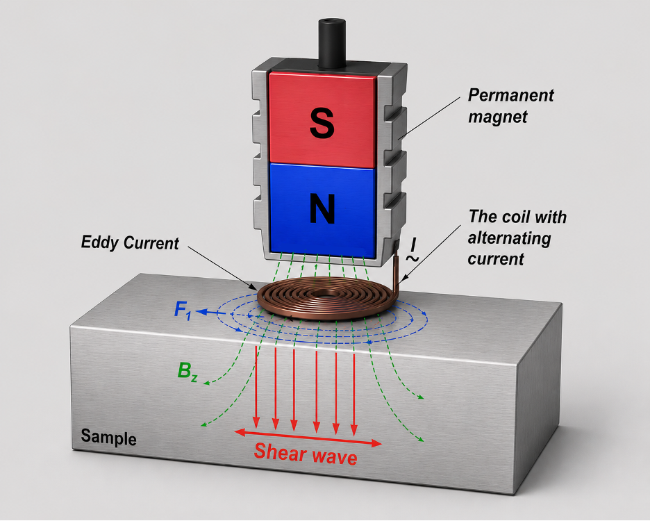
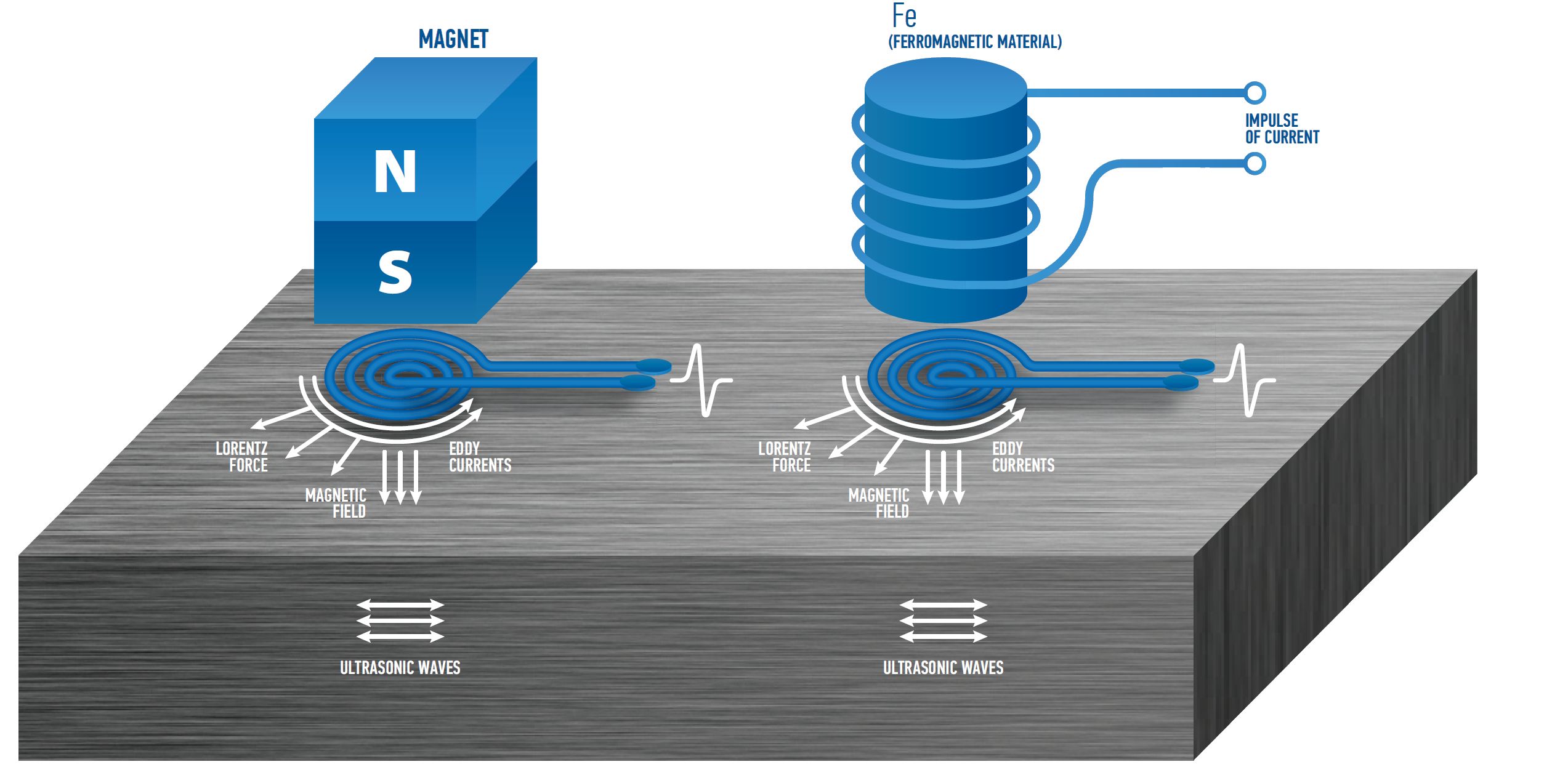
EMAT removes the couplant from the equation. Instead of pushing a wave across the surface from outside, it generates the wave inside the metal itself, and that changes what an inspection can do.
How EMAT works
An EMAT has two parts: a radio-frequency coil and a static bias magnet, and the magnet can be a permanent magnet or an electromagnet. The coil sits close to the surface and drives a high-frequency current. That current induces eddy currents in the skin depth of the metal, and those eddy currents interact with the bias field through the Lorentz force to launch a wave directly inside the part. Nothing is pressed against the surface and no couplant carries the wave across. The metal itself becomes the source.
On ferromagnetic metal — carbon steel and most pipework — a second mechanism joins in. The alternating field makes the steel’s magnetic domains change shape slightly, an effect called magnetostriction, and that adds to the wave. For a PPM-EMAT on mild steel, the magnetostrictive contribution has been modelled and measured at roughly 55% of the Lorentz contribution in the static case [6]. It is a major second source, not the dominant one, and it is why EMAT signals on steel are usually stronger than on aluminium, where only the Lorentz mechanism is available.
Why no couplant changes the operational envelope
Removing the couplant removes the biggest bottleneck in field inspection. EMAT reads through paint, light coatings, rust, scale, and oxide, so most of the surface prep that piezo demands goes away. It tolerates a small lift-off, typically zero to 3 mm in the field and up to about 10 mm in the lab, though the signal falls off quickly as the gap grows. The peak frequency also shifts about 100 kHz for every millimetre of lift-off on a Rayleigh-wave EMAT [7], which the instrument has to track.
Temperature is the other envelope change. Liquid couplant gives out around 150 °C. EMAT keeps working well past that because nothing touches the hot surface but the probe face and its standoff. Thickness measurements on low-carbon steel have been demonstrated at 450 °C with no cooling at all [8], and water-cooled designs push toward 1,000 °C. That puts live refinery lines, boiler water-walls, hot-rolled steel in the mill, and insulated in-service pipework within reach without a shutdown. This is the technology behind instruments like the EMAT thickness gauge in our own line.
Coil geometries and wave mode selectivity
EMAT picks its wave mode from the shape of the coil and the direction of the bias field, not from a wedge. A spiral pancake coil under a normal field drives a radial Lorentz force and makes normal-incidence shear waves for thickness gauging and corrosion mapping. A racetrack coil under periodic permanent magnets selects Lamb modes, with the symmetric or antisymmetric mode set by where the wires sit relative to the magnets. A meander-line coil fixes the wavelength by its pitch and generates angled bulk waves, Rayleigh surface waves, or specific guided modes. The practical payoff is that shear-horizontal waves, which are hard to make with piezo in a scanning setup, are routine with EMAT. The same magnetostrictive effect drives a close cousin, the magnetostrictive transducer, which launches guided waves along a pipe to screen tens of metres from a single position.
Permanent magnets vs pulsed electromagnets
This is where the bias source becomes a field decision, not just a design detail. Permanent magnets, usually NdFeB or samarium-cobalt for higher temperature, made early EMAT practical. They also drag hard on steel, so the inspector cannot slide the probe smoothly; they collect shavings, scale, and debris on the face between readings; and the NdFeB grade weakens as the surface heats toward its Curie point.
A pulsed electromagnet turns the bias field on only for the microsecond of the measurement. Between pulses there is no field, so there is no magnetic drag during a scan, nothing pulls debris onto the face, and there is no permanent magnet to weaken when the steel is hot. Permanent-magnet probes remain the right answer for point measurements and lower-cost work, and pulsed-electromagnet probes are the path for continuous scanning on hot or dirty steel.
Limitations
EMAT’s limitations are physical and well documented. Generating sound electromagnetically is less efficient than the piezoelectric effect. The one-way insertion loss is 40 dB or more under ASTM E1774-17, which means a lower signal-to-noise ratio than piezo on the same reflector. Higher pulser voltages, broadband matched receivers, and tone-burst excitation claw some of that back, but the floor is real. EMAT also works only on conductive metal, so plastics, composites, glass, and ceramics are out. There is a dead zone on the first echo, around 6 mm in steel, so thickness work reads between the second and third back-wall echoes. The probes cost more than piezo, and the permanent-magnet versions are heavier.
None of this changes the basic fact that EMAT works only because the part is metal. Step onto concrete and neither couplant nor electromagnetics helps, which is the problem the next family was built to solve.
Dry-point-contact (DPC) transducers and arrays
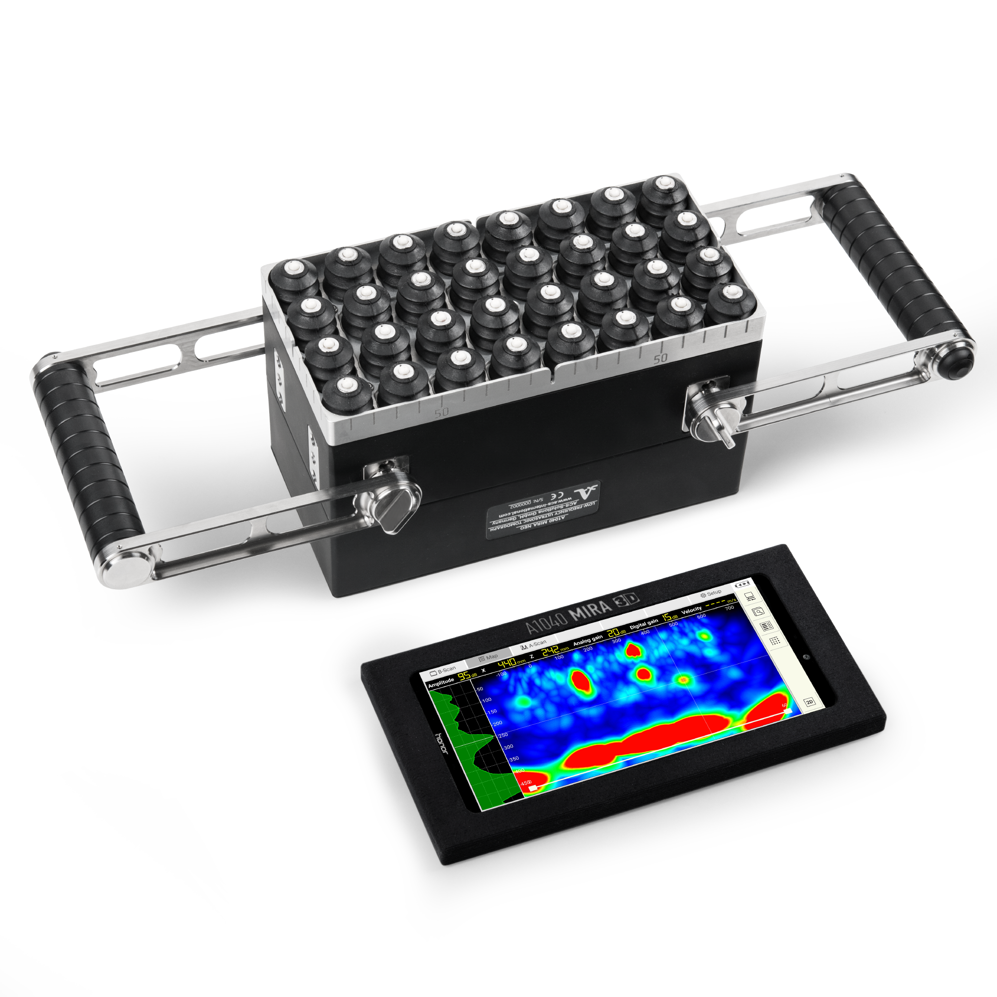
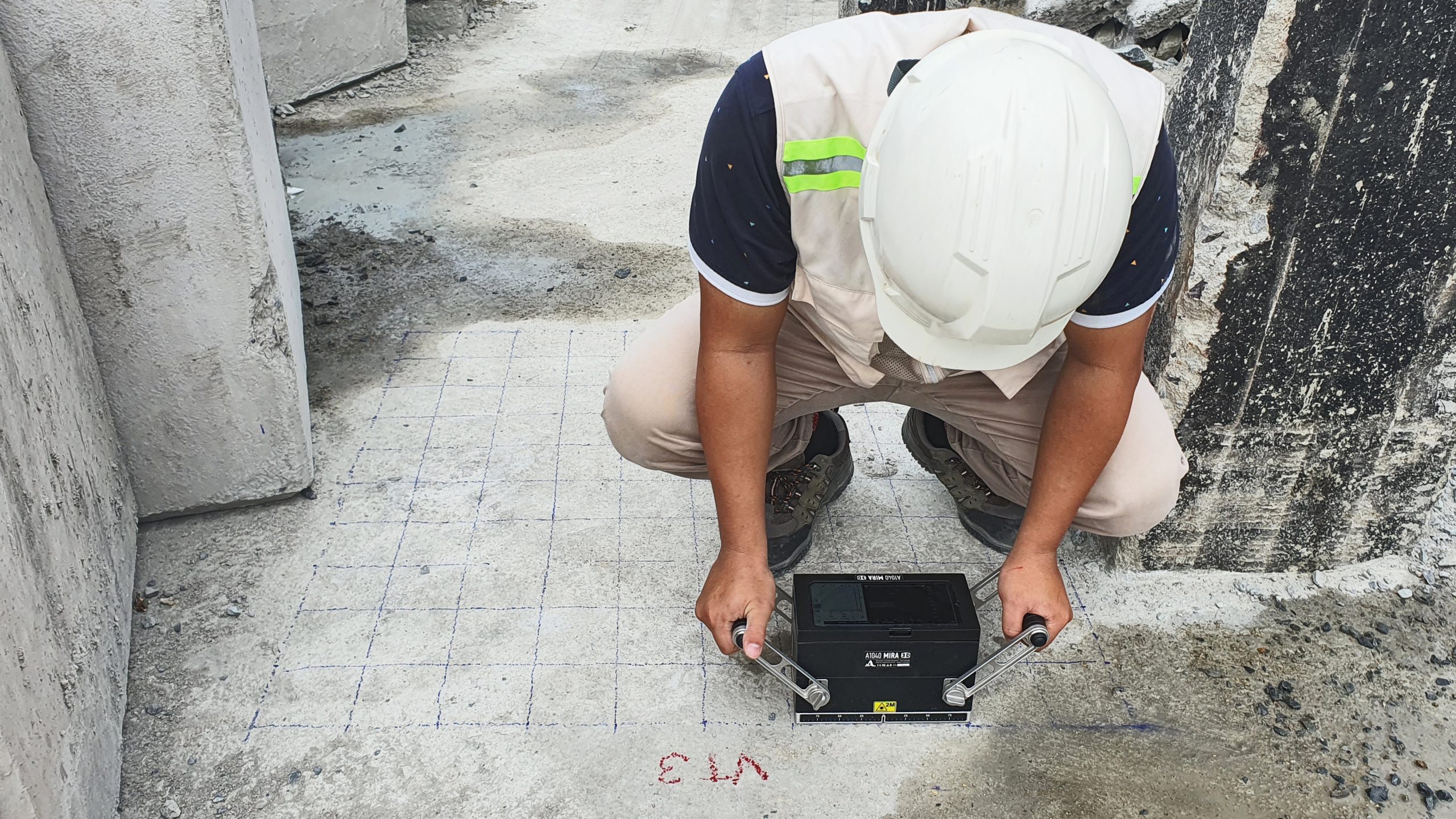
Neither of the families above works on concrete. It does not conduct, so EMAT has nothing to work with, and in many cases it is too rough and porous for liquid couplant to stay put. Inspecting concrete from one side needed a different idea, and dry point contact is it. This section draws on published manufacturer research in the field [9].
Why concrete demands a different transducer
Concrete is not a uniform solid. It is a matrix of cement paste and coarse aggregate, shot through with air voids, rebars, and ducts. High-frequency ultrasound scatters off all of that, and the signal-to-noise floor collapses before the wave reaches anything useful. The fix is to drop the frequency. Working in the low range, around 50 kHz for concrete arrays and broadly from tens of kilohertz upward, keeps the wavelength larger than the typical aggregate, so the wave travels through the matrix instead of bouncing off every stone [9].
Couplant is the second problem. A liquid film cannot hold on a rough, porous surface, because the gel drains into the pores and the contact turns inconsistent. The dry point contact answer is a hard, wear-resistant ceramic tip, spring-loaded, pressed onto the surface. The tip is much smaller than the wavelength, so it acts as a single point that bridges the surface roughness and injects energy through a small, high-pressure contact, with no liquid and no surface prep [9].
Why shear waves matter for concrete inspection
A useful property falls out of the dry-point-contact mechanism. It naturally generates shear waves as well as longitudinal ones [9]. That matters because cracks behave as directional reflectors, and shear waves read them cleanly. A shear wave diffracts around a crack tip without converting to other modes, so the return signal stays readable and the depth of a vertical crack can be measured from a single side. Longitudinal waves split into secondary modes on the same defect and muddy the picture. Clean shear-wave crack sizing from one side is a capability ordinary piezo on concrete cannot match.
From a single tip to an array
One tip at low frequency has coarse spatial resolution. The answer is an array of them. Each element rides on its own spring, so the array keeps contact across a rough or curved surface without losing elements. The array then runs Full Matrix Capture, where every element transmits in turn while all elements receive, and the recorded set is reconstructed with the Total Focusing Method, which focuses at every image point rather than at one fixed depth. In concrete, plain TFM is usually backed by SAFT, the synthetic aperture technique that holds up in the noisy, scattering conditions concrete creates [9]. Half-skip TFM adds a supplementary path that bounces off the back wall to size vertical surface-breaking cracks more reliably than direct imaging [10]. The result is a real-time three-dimensional image of the inside of the structure, built from one side, showing rebar, voids, ducts, delaminations, the back wall, and cracks. High-end manufacturer arrays carry up to 64 independent elements.
Where DPC tomography is the only practical option
Most civil structures give you one side to work from, and that is the case DPC tomography is built for. Bridge decks, tunnel liners, slabs, and walls all get inspected from the surface you can reach. It verifies grouting in the tendon ducts of post-tensioned structures, finds voids and honeycomb in load-bearing elements, and gauges slab thickness where there is no access to the far face.
UPVT versus UPET
Two methods get confused here, and they are not the same. Ultrasonic pulse velocity testing, or UPVT, sends a pulse from a transmitter on one face to a receiver on another and times it. The result is one velocity number, an integrated indicator of concrete quality and uniformity — the kind of measurement delivered by a couplant-free UPVT instrument. Ultrasonic tomography, also called ultrasonic pulse-echo tomography (UPET), is an imaging method returning a 2D / 3D representation of the inspection volume rather than a single number. They answer different questions, and manufacturers build instruments for both. They are not substitutes for each other.
Limitations
The low frequency that makes concrete workable also caps the resolution. DPC tomography resolves features at the centimetre-to-decimetre scale, not the millimetre scale. The surface can be rough, but it still cannot be loose, flaking, or covered by decorative finishing materials. Penetration depends heavily on the concrete itself. Up to about 2 m is typical, and the highest-end arrays reach roughly 6 m in good-quality concrete with signal boosting, while a heavily attenuating mix or multiple rebar layers cuts that down. DPC also still asks for a hand on the surface, one position at a time. The next section covers two families that drop even that — one by crossing the air gap without contact, the other by staying permanently in place.
Air-coupled and embedded transducers
Two more families drop contact with the surface entirely. One crosses the air gap without touching the part, and the other stays bonded in place for years. They cover jobs the contact families cannot.
Air-coupled transducers
Air-coupled transducers send the wave through the air itself, with no contact and no couplant. The obstacle is the same impedance mismatch from the fundamentals, except the wave now crosses two air-to-solid boundaries instead of one, so the total path loss runs to 100 to 150 dB [11]. Designs fight that with heavily impedance-matched piezocomposite elements, increasingly with micromachined elements, and with high-power tone-burst excitation and pulse compression to recover signal. Because air damps high frequencies hard, air-coupled work stays low, roughly 50 to 800 kHz [11], and most field setups use through-transmission, with a transmitter on one side and a receiver on the other. That needs access to both sides of the part, which suits panels moving down a production line but rules out one-sided field work. Single-sided air-coupled pulse-echo is possible but harder.
Its strength is parts that cannot take a liquid. Foam-cored sandwich panels, CFRP and GFRP composites, ceramics, wood, and food or packaging all inspect well with air coupling, and it picks up delaminations, disbonds, and impact damage in layered structures where immersion is not acceptable or the geometry is awkward.
Embedded transducers for active and passive monitoring
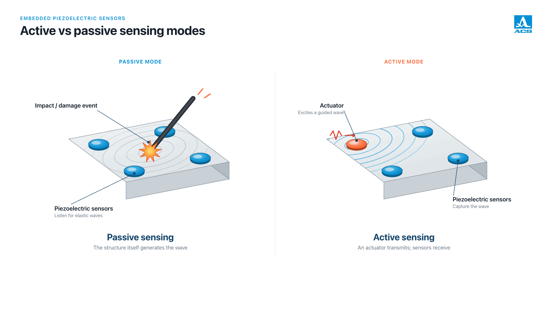
Embedded transducers are installed once and left in place, cast into or bonded onto a structure to watch it over time instead of inspecting it on a visit. They work in two modes. In active mode, the sensor pulses on a schedule and tracks how transit time or amplitude drifts, which exposes internal damage, corrosion, or voids as they develop. In passive mode, the sensor stays quiet and listens for the acoustic emission a growing flaw gives off, catching events as they happen rather than at the next scheduled scan. Active sensing answers how a structure is changing over time; passive sensing answers when something just happened, and many installations run both together.
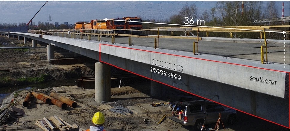
The use cases are long-lived assets where a permanent eye beats periodic visits, like bridges, dams, post-tensioned slabs, and repair zones watched after a fix. The wider shift behind this is from one-off inspection toward permanent monitoring, where cheap IoT links and multi-year battery life let a network of installed sensors feed data back to the office for threshold alerting. The payoff is catching a problem as it grows rather than at the next scheduled visit. The approach is field-proven: researchers at BAM installed embedded ultrasonic transducers of this type inside a 36 m section of a road bridge in Germany and monitored load and temperature effects with coda wave interferometry [12], and follow-up work on the same bridge demonstrated noise-reduction methods for long-term monitoring [13].
That completes the transducer families that carry day-to-day inspection. With the methods and the hardware both covered, the next section sets the families side by side on the parameters that decide a job: frequency, couplant, temperature, speed, and cost.
Performance comparison
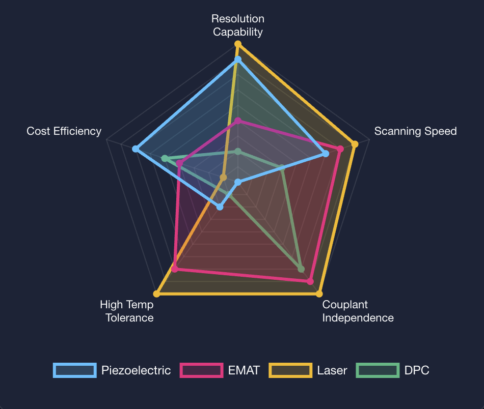
Here is the comparison side by side. The table covers the four core generation methods plus PAUT and air-coupled, on the parameters that usually decide a procurement: frequency, couplant, surface preparation, speed, sensitivity, temperature, SNR, lift-off, cost, portability, and training.
| Parameter | Piezoelectric | PAUT | EMAT | Laser | DPC array | Air-coupled |
|---|---|---|---|---|---|---|
| Useful frequency | 0.5–25 MHz | 0.5–20 MHz | 0.1–10 MHz | 0.1–50 MHz | 10–400 kHz | 50–800 kHz |
| Couplant | Yes | Yes | No | No | No | No |
| Surface prep | Smooth, clean | Smooth, clean | Minimal, paint and scale OK | Paint OK | None, tolerates rough concrete | None |
| Scan speed | Moderate | High | High | High | Moderate | High |
| Sensitivity to small flaws | High | High | Reduced | Moderate to high | Limited by long wavelength | Limited |
| Operating temperature | -20 to 50 °C, to ~550 °C with high-temp ceramics | -20 to 50 °C | ~450 °C uncooled, to ~1,000 °C cooled | Any (non-contact) | Ambient | Ambient |
| SNR | High | High | Lower (high insertion loss) | Moderate, speckle-limited | Limited by concrete scattering | Limited |
| Lift-off tolerance | None (contact) | None (contact) | 0–3 mm | Standoff of cm to metres | Spring contact absorbs roughness | Tens of mm |
| Capital cost | Low | Moderate to high | High | Very high | Moderate to high | Moderate to high |
| Portability | Excellent | Good | Good, heavier probe | Poor | Good, handheld | Moderate |
| Operator training | Level II/III | PAUT Level II/III | EMAT add-on training | Specific plus laser safety | Specific | Specific |
A few rows carry most of the decision. The couplant row splits the families in two — piezo on one side and everything else on the other — and that single difference drives most of the hard-environment choices. The temperature row separates the families that stop near 50 °C from EMAT and laser, which keep working into the hundreds of degrees. Sensitivity runs the other way, with contact piezo holding the edge on the small flaws that the couplant-free families give up some signal to reach. Cost and training track roughly with how specialised the method is.
The frequency split is not arbitrary. It is the resolution-versus-penetration tradeoff from the fundamentals, played out across materials. Concrete forces the low end and pays for it in resolution, while thin metal allows the high end and the fine detail that comes with it. That is why the families sort by frequency before they sort by anything else.
Read the table as a profile of relative strengths, not a picture of market share. By volume, ordinary contact piezoelectric still does most of the ultrasonic inspection in the world, and nothing here changes that. What the table shows is where each family pulls ahead when the conditions suit it. It also hides as much as it shows, because the right column for a given job shifts with the material, the geometry, the code you inspect to, and how often you need the reading.
No family leads on every axis. Piezo leads on resolution and cost, EMAT and laser lead on couplant independence and temperature, and DPC owns the low-frequency concrete corner. A table cannot pick for you, because the right answer depends on the job in front of you. The next section turns this comparison into a set of questions you can run against a real inspection — the kind an engineer already asks when scoping the work.
Choosing the right transducer: a practical framework
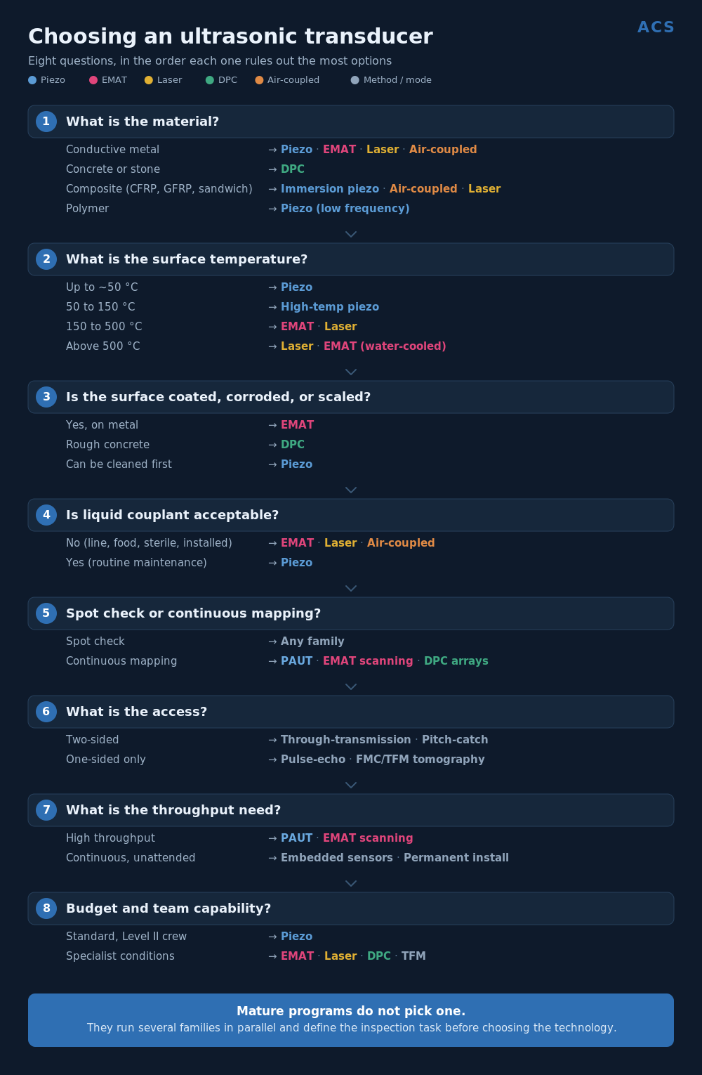
Those questions have a rough order, because some of them rule out more options than others. Work them in sequence and the field narrows fast.
Start with the material, because it eliminates the most at once. Conductive metal keeps piezo, EMAT, and laser on the table. Concrete and stone send you straight to DPC. Composites like CFRP, GFRP, and foam-cored sandwich point to immersion piezo, air-coupled, or laser. Polymers usually mean piezo at a lower frequency. One answer, and most of the options are already gone.
Then read the environment the surface presents. Temperature sorts the families quickly. Up to about 50 °C, piezo is fine. To 150 °C, a high-temperature delay-line probe holds. Past that, EMAT takes over, and non-contact laser ultrasonics reaches the highest extremes as a specialist option. Surface condition is the next cut. Coated, corroded, or scaled metal favours EMAT, which reads through paint and light scale, where piezo would need the surface cleaned first and DPC simply works on rough concrete as it is. After that, ask whether liquid couplant is even acceptable. On a production line, in a food or sterile setting, or anywhere a sensor stays installed, couplant is a non-starter, and EMAT or air-coupled win on that alone, with non-contact laser a specialist alternative. For routine maintenance on accessible steel, gel-coupled piezo is still the cheapest good answer. If the task is straightforward thickness gauging on steel, our ultrasonic thickness gauges category is the natural starting point.
Next comes how the data has to be collected. A single spot check runs on almost anything. Continuous mapping points to electronically steered PAUT, couplant-free EMAT scanning, or DPC arrays for one-sided concrete tomography. Access settles the next branch. Two-sided access opens through-transmission and pitch-catch, while one-sided-only work means pulse-echo or FMC/TFM tomography. High throughput pushes toward PAUT or EMAT scanning, and a need for continuous unattended readings points to embedded or permanently installed sensors.
The last question is about budget and the team you have. Standard surveys with a Level II workforce stay on piezo, where the training, calibration blocks, and procedures already exist. Specialist conditions are exactly what justify the extra cost and training of EMAT, laser, DPC, or full TFM.
Mature inspection programs do not pick one technology and standardise on it. They run several transducer families in parallel and choose per task, because the trade-offs this article keeps drawing never collapse into a single winner. The wrong move is to choose a technology before the inspection task is defined. That mix of technologies is also where the field is heading, only more so — the subject of the next section.
Where the field is heading
The trends all point the same way: toward more transducer families, used more automatically, more of the time. None of them retire the trade-offs in this article. They make it easier to run several families together and to leave them running.
The biggest shift is in acquisition. Full Matrix Capture with TFM is moving from a high-end weld technique to a default mode, as GPU acceleration removes the compute cost that used to hold it back. Arrays themselves are getting more adaptable, with flexible and conformable probes that contour to elbows, T-joints, and compound curves and recompute their focal laws on the fly as the surface changes.
Automation is the next front. PAUT crawlers run long welds, pipe crawlers carry corrosion-mapping arrays, wall-climbing platforms cover tank shells, and drones carry dry-coupled or laser probes onto stacks and storage tanks. Alongside the hardware, AI-assisted interpretation is starting to cut review time on large data sets by classifying A-scan, S-scan, and C-scan data, though it stays an aid to a trained inspector rather than a replacement, since the call on a real defect still belongs to a qualified person.
The other shift is from inspection toward monitoring. Permanently installed transducers feed battery-powered wireless networks that report back over multi-year deployments, so a structure is watched continuously instead of on a visit. Instruments are converging too, running piezo and EMAT probes from one unit and acquiring PAUT and TOFD together. Pulsed-electromagnet EMAT is spreading as power electronics improve, because it removes EMAT’s worst field-handling problems. Further out, micromachined transducers — CMUT and PMUT — remain a developmental front for air-coupled work rather than a deployed standard.
Key takeaways
- Every ultrasonic inspection starts with a transducer choice. Get it wrong and no amount of instrument quality recovers the inspection.
- The core families exist because no single mechanism wins on surface condition, temperature, sensitivity, and access at the same time. Each owns a different corner of that trade-off.
- Piezoelectric is the default for clean, ambient-temperature metal. EMAT takes over when couplant fails or the surface is hot or coated. DPC is the answer for concrete. Air-coupled and embedded transducers cover non-contact composite work and permanent monitoring.
- Inspection methods like PAUT, TOFD, FMC/TFM, guided wave, and tomography pair differently with each family. The method-versus-transducer matrix is the fastest way to scope a procedure.
- Mature programs do not standardise on one technology. They run several families in parallel and choose per task.
Conclusion
Choosing a transducer is not about finding the best probe on paper — it is about matching the probe to the reality of the asset. The method tells you what to look for; the transducer decides whether you can actually see it. Start with the material, weigh temperature and surface against sensitivity and cost, and let each answer narrow the field until one family is the obvious fit.
At Delta Test Technologies we work with ultrasonic instruments across the transducer spectrum described in this guide — from conventional piezoelectric thickness gauging to couplant-free EMAT and dry-contact concrete instruments. If you are scoping an inspection and want help matching the hardware to the task, reach out to us — the right transducer choice at the start saves more than any instrument setting at the end.
Frequently asked questions
What are the main types of ultrasonic transducers used in NDT?
Three core transducer families plus laser excitation. Piezoelectric is the workhorse for metal and composites, EMAT is the couplant-free choice for hot or coated metal, DPC handles concrete, and laser excitation is a non-contact niche. Two more cover specific gaps: air-coupled for composites, and embedded sensors for permanent monitoring. Each one generates sound by a different physical mechanism, which is what suits it to different conditions.
What is the difference between a piezoelectric and an EMAT transducer?
A piezoelectric probe presses an active ceramic against the part and needs a liquid couplant to carry the wave across. EMAT generates the wave inside the metal itself with an electromagnetic field, so it needs no couplant and reads through paint, scale, and heat. The trade-off is sensitivity. Piezo is more sensitive on clean metal, while EMAT gives up some signal in exchange for working in hard conditions.
Which ultrasonic transducer is best for inspecting concrete?
DPC, the dry point contact transducer. Concrete scatters high-frequency sound and will not hold liquid couplant, so concrete inspection uses low-frequency, spring-loaded dry-contact tips, usually in arrays that build a 3D image of the interior from one side.
Can ultrasonic testing be done without couplant?
Yes. EMAT, laser, air-coupled, and DPC transducers all work without liquid couplant, each in a different way. EMAT uses electromagnetic coupling on metal, laser is fully non-contact, air-coupled sends the wave through the air, and DPC uses a dry contact tip. Piezoelectric is the family that still needs gel or oil.
What ultrasonic transducer works at high temperature?
EMAT, mainly. Standard piezoelectric fades above about 50 °C, and liquid couplant boils near 150 °C. EMAT works to several hundred degrees uncooled and to around 1,000 °C with water cooling, while non-contact laser ultrasonics, a specialist option, has no contact temperature limit at all. High-temperature piezo probes with delay lines cover the middle range.
When should I use an air-coupled transducer?
When the part cannot take a liquid and you can reach both sides. Air-coupled transducers are non-contact and suit foam-cored sandwich panels, CFRP and GFRP composites, ceramics, and wood, usually in through-transmission. They are not the choice for precision metal gauging or small flaws, because the air gap costs a lot of signal.
Can EMAT transducers measure wall thickness?
Yes, and it is one of their main jobs. EMAT gauges remaining wall thickness on hot, coated, or corroded steel without couplant, which is why it is common on in-service pipework and pressure equipment. There is a small dead zone on the first echo, so readings are usually taken between later back-wall echoes.
How do I choose the right ultrasonic transducer for my inspection?
Start with the material, then work through temperature, surface condition, whether couplant is acceptable, spot check versus mapping, access, throughput, and budget. Each answer narrows the field. Mature inspection programs run several transducer families and choose per task rather than standardising on one.
References
Manufacturer-published research is the first-choice citation in this article and appears as [9]. All sources below were checked to confirm they exist and that the figure or claim cited to them is actually supported.
[1] “Ultrasonic calibration and certification of V1 and V2 type reference standard blocks for use in Non-Destructive Testing,” Journal of Physics: Conference Series, vol. 279, 012029, 2011. Confirms the EN ISO 7963 steel calibration-block velocities (longitudinal 5,920 m/s, transverse 3,255 m/s). Available: https://iopscience.iop.org/article/10.1088/1742-6596/279/1/012029
[2] “Acoustic Impedance, an overview,” ScienceDirect Topics (Engineering). Available: https://www.sciencedirect.com/topics/engineering/acoustic-impedance
[3] “The Choice of Torsional or Longitudinal Excitation in Guided Wave Pipe Inspection,” NDT.net, IranNDT 2018. Available: https://www.ndt.net/article/IranNDT2018/papers/1077-IRNDT-Paper-for-IRNDT-2018-The-choice-of-torsional-or-longitudinal-excitation-in-guided-wave-pipe-inspection.pdf
[4] G. Splitt, “Piezocomposite Transducers, a Milestone for Ultrasonic Testing,” NDT.net, July 1996. Available: https://www.ndt.net/article/splitt/splitt_e.htm
[5] Y. Zhang et al., “Design and comparison of PMN-PT single crystals and PZT ceramics based medical phased array ultrasonic transducer,” Sensors and Actuators A: Physical, 2018. Available: https://www.sciencedirect.com/science/article/abs/pii/S0924424718312895
[6] “Influence of Magnetostriction Induced by the Periodic Permanent Magnet Electromagnetic Acoustic Transducer (PPM EMAT) on Steel,” Sensors (MDPI), vol. 21, no. 22, 7700, 2021. Available: https://www.mdpi.com/1424-8220/21/22/7700
[7] P. Yi, K. Zhang, Y. Li, X. Zhang, “Influence of the Lift-Off Effect on the Cut-Off Frequency of the EMAT-Generated Rayleigh Wave Signal,” Sensors (MDPI), vol. 14, no. 10, 2014. Available: https://www.mdpi.com/1424-8220/14/10/19687
[8] “Shear Wave EMAT Thickness Measurements of Low Carbon Steel at 450 °C Without Cooling,” AIP Conference Proceedings, vol. 1806, 050009, 2017. Available: https://pubs.aip.org/aip/acp/article/1806/1/050009/976904
[9] A. Bulavinov, A. Samokrutov, R. Pinchuk, V. Shevaldykin, “Application of Dry-Point-Contact Ultrasonic Transducers for Non-Destructive Material Testing,” Journées COFREND 2026, Lyon, 19-21 May 2026. Published manufacturer research on DPC technology.
[10] “Imaging of Vertical Surface-Breaking Cracks in Concrete Members Using Ultrasonic Shear Wave Tomography,” 2023. Available: https://pmc.ncbi.nlm.nih.gov/articles/PMC10709634/
[11] B. Hillger et al., “Air-coupled Ultrasonic Testing, Method, System and Practical Applications,” NDT.net, ECNDT 2014. Available: https://www.ndt.net/events/ECNDT2014/app/content/Paper/482_Hillger.pdf
[12] X. Wang, E. Niederleithinger, I. Hindersmann, “The installation of embedded ultrasonic transducers inside a bridge to monitor temperature and load influence using coda wave interferometry technique,” Structural Health Monitoring, vol. 21, no. 3, pp. 913–927, 2022. Available: https://www.ndt.net/article/sage_shm/papers/wang-et-al-2021-the-installation-of-embedded-ultrasonic-transducers-inside-a-bridge-to-monitor-temperature-and-load.pdf
[13] X. Wang, J. Chakraborty, E. Niederleithinger, “Noise Reduction for Improvement of Ultrasonic Monitoring Using Coda Wave Interferometry on a Real Bridge,” Journal of Nondestructive Evaluation, vol. 40, art. 14, 2021. Available: https://link.springer.com/article/10.1007/s10921-020-00743-9
Standards referenced inline
- ASTM E1774, Standard Guide for Electromagnetic Acoustic Transducers (EMATs). Cited for the one-way insertion loss figure (40 dB or more) in the EMAT section.
- ASTM E2700, Standard Practice for Contact Ultrasonic Testing of Welds Using Phased Arrays. Cited in the piezoelectric section.
- ISO 17640, Non-destructive testing of welds, Ultrasonic testing. Cited in the piezoelectric section.
- EN ISO 7963, Non-destructive testing, Ultrasonic testing, Specification for calibration block No. 2. Source of the steel velocities in the basics section (see [1]).